
45 Nm is a torque cap, not a universal output
At the 10.5 kW power ceiling, 45 Nm corresponds to about 2228 RPM. Below that speed the torque cap limits power; above it the power cap limits torque.
Evidence: Derived from P = torque x RPM / 9549.
Hybrid sizing tool and engineering report
Enter voltage and speed to screen available power, torque, current, and cooling risk before reading the evidence-backed sizing report.
Searching for a 10kw axial flux motor? Use the canonical axial flux electric motor guide to compare topology fit, evidence limits, and 10 kW-class sizing tradeoffs.
Peak power
10.5 kW
Peak torque
45 Nm
Reviewed
Jul 2026
Decision summary
At the 10.5 kW power ceiling, 45 Nm corresponds to about 2228 RPM. Below that speed the torque cap limits power; above it the power cap limits torque.
Evidence: Derived from P = torque x RPM / 9549.
At 10.5 kW output and 95% nominal efficiency, a 48 V DC bus implies roughly 230 A input current before transient, cable, and inverter margins.
Evidence: Calculator assumption table and current formula.
Compact AFPM motors can deliver high peak density, but continuous power depends on winding temperature, stator cooling path, and controller limits.
Evidence: Public AFPM manufacturer data and thermal design practice.
Heavy-lift UAV takeoff, light EV acceleration, and compact robotics benefit most. Marine cruise and repeated stall duty need lower continuous sizing.
Evidence: Application boundary table below.
The page uses public AFPM benchmarks to set expectations, while exact weight, efficiency map, and S1 rating remain sample-test items.
Evidence: Source disclosure table reviewed on July 17, 2026.
A public commercial karting reference lists a 10.5 kW, 45 Nm, 48 V, 350 A controller combination, which makes karting relevant for comparison. It does not prove the same continuous rating, topology, or thermal margin for an AFPM motor.
Evidence: BIZ Karts EcoVolt GT product page reviewed July 17, 2026.
Architecture
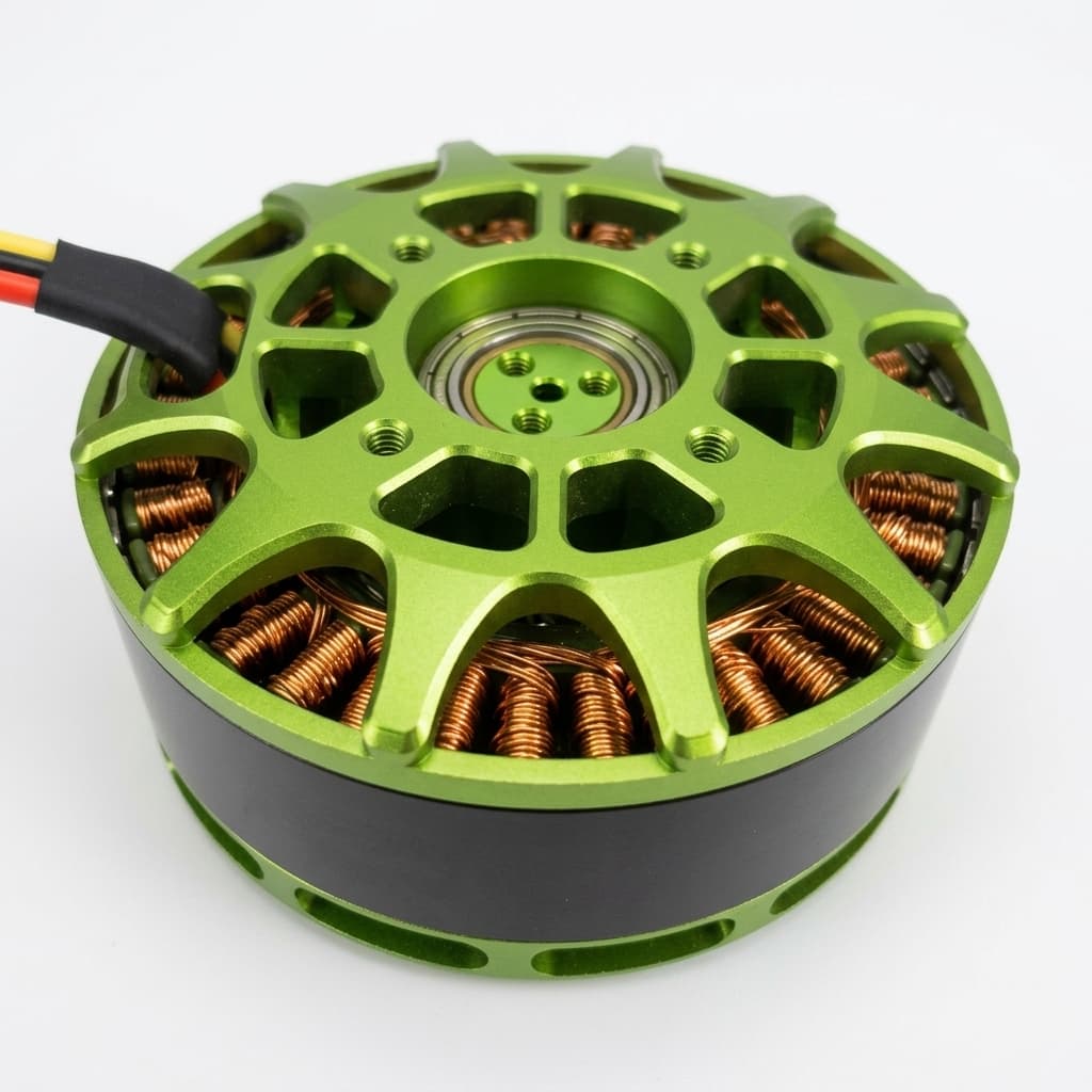
A 10.5 kW 45 Nm permanent magnet axial flux brushless motor uses disc-shaped rotors and an axial magnetic path. The active radius can be larger than a similar-length radial motor, which supports high direct torque in a short package. That benefit is real, but it does not remove thermal, rotor, inverter, or bearing checks.
Operating envelope
The calculator is intentionally deterministic: the same voltage and RPM return the same power, torque, current, and warning state. Use it as a first-pass screen, then ask for a torque-speed curve and efficiency map for the exact winding and cooling package.
Known, estimated, unknown
Numeric values below are separated by confidence level to avoid presenting benchmark assumptions as final datasheet facts.
| Item | Value | Confidence | Buyer action |
|---|---|---|---|
| Peak output power | 10.5 kW | Target rating | Confirm duration, cooling condition, and voltage in RFQ. |
| Peak shaft torque | 45 Nm | Target rating | Check whether the duty point is below or above 2228 RPM base speed. |
| Continuous output power | 5-6 kW planning estimate | Needs sample test | Request S1 data at ambient temperature, airflow, and mounting condition. |
| Efficiency | 94-96% planning target near optimal load | Benchmark-derived | Request an efficiency map, not a single peak number. |
| Weight | N/A until drawing is released | Unknown | Do not lock aircraft or vehicle mass budget until housing, shaft, and cooling are defined. |
Method
The tool avoids hidden lookup tables. It uses first-principles motor sizing math plus explicit boundaries for current and thermal risk.
| Variable | Formula or trigger | Why it matters |
|---|---|---|
| Power from torque and speed | kW = Nm x RPM / 9549 | Shows whether 45 Nm can reach the requested power at the chosen RPM. |
| Torque from power and speed | Nm = kW x 9549 / RPM | Shows how torque falls after the 10.5 kW ceiling is reached. |
| Estimated DC current | A = output watts / (V x 0.95) | Screens inverter, cable, fuse, and connector sizing pressure. |
| Thermal warning | Flag when power >90%, torque >98%, or current >180 A | Separates brief peak use from points that need cooling evidence. |
Evidence layer
Last reviewed on July 17, 2026. Public sources support topology and benchmark context; exact production numbers still require supplier validation for this motor.
| Source | Reviewed | Used for | Limit |
|---|---|---|---|
| EMRAX official motor data | July 17, 2026 | Comparable AFPM product-class benchmark for peak/continuous ratings, efficiency framing, and the need to separate peak from continuous duty. | Competitor motor family, not this 10.5 kW 45 Nm SKU; use only as context. |
| Evolito axial-flux technology notes | July 17, 2026 | Supports the aviation-oriented high power density use case and the importance of integrated motor, inverter, and thermal design. | Company technology positioning, not a directly comparable 10.5 kW datasheet. |
| YASA axial-flux technology explanation | July 17, 2026 | Supports the topology explanation: short axial package, high torque density, and direct-drive potential versus radial-flux layouts. | Architecture reference only; final capability still depends on geometry and cooling. |
| AFPM Motor calculator formula | July 17, 2026 | Reproducible operating-point math for torque, speed, power, current, and boundary warnings on this page. | A sizing screen, not a substitute for dyno, thermal, EMC, or inverter validation. |
| BIZ Karts EcoVolt GT product page | July 17, 2026 | Direct commercial karting reference for the listed 10.5 kW / 45 Nm permanent magnet brushless motor and 48 V / 350 A motor-controller combination. | Not an AFPM Motor datasheet and not proof of industry-wide practice; verify motor topology, controller current type, battery current, and thermal duty cycle before using it as an AFPM selection baseline. |
Related engineering paths
Use these internal references to move from the calculator result to a product family, use-case boundary, validation gate, or RFQ.
Estimate size, torque, and pole count for low-speed generators.
Phase current & inverter matching calculator.
Estimate performance for a space-constrained 100mm diameter generator.
Compare the broader custom motor program scope.
Review the short axial package architecture used for torque.
Check vehicle duty-cycle inputs before selecting a winding.
Map takeoff, climb, and hover power against thermal limits.
Use dyno, thermal, and inspection data before production lock.
See our sizing tool and report covering the 10 kW to 100 kW classes.
Screen feasibility for extreme 1000 hp / 745 kW axial flux applications.
Screen a 100kW shaft requirement with separate duty and cooling evidence.
Evaluate 10kW axial flux motors for light EVs, drones, and motorcycles.
Evaluate 20kW axial flux motors for light EVs, drones, and motorcycles.
Share voltage, speed, package, duty cycle, and sample quantity.
Use-case fit
| Application | Default point | Fit | Main risk | Next data to send |
|---|---|---|---|---|
| Heavy-lift UAV | 96 V, 2000 RPM | Strong for takeoff and climb | Hover thermal rise and propeller load curve uncertainty | Share thrust target, prop diameter, hover duty, and airflow path. |
| Light EV / motorcycle | 96 V, 3000 RPM | Good for acceleration and compact packaging | Continuous road-load heat and controller current limit | Share wheel size, reduction ratio, gradeability, and cooling volume. |
| Marine propulsion | 96 V, 1800 RPM | Possible if sized below peak | Cruise is continuous and sealing can trap heat | Share prop load curve, enclosure rating, and corrosion requirement. |
| Industrial robotics | 72 V, 1200 RPM | Useful where flat package and direct torque matter | Repeated stall, holding torque, and low-speed heating | Share torque profile, hold time, encoder needs, and safety factor. |
| Commercial electric go-karts | 48 V, 2200 RPM | Relevant reference point when the kart uses a 48 V pack and a controller sized for high burst current | Intense start-stop thermal cycling and rental fleet abuse | Share battery capacity, controller battery and phase current limits, gearing, session length, cooldown time, and cooling airflow. |
Risk and tradeoff
The most common mistake is selecting by peak kW and Nm alone. Use the risk table to decide what must be validated before prototype release.
| Risk | Severity | Trigger | Mitigation |
|---|---|---|---|
| Misusing peak rating as continuous rating | High | Sizing 10.5 kW as 100% duty cycle without temperature data | Request S1/S2 ratings and winding temperature rise at the exact cooling condition. |
| Undersized inverter and cabling | High | 48 V or low-voltage pack at high power | Raise bus voltage, derate current, or validate connectors, fusing, and phase leads. |
| Rotor mechanical overspeed | Medium | Operating above 4500 RPM or changing propeller/wheel load | Confirm rotor stress margin, balancing, containment, and maximum electrical frequency. |
| Scene mismatch | Medium | Marine cruise, robot hold torque, or low airflow packaging | Use lower continuous sizing or add liquid/forced cooling and thermal sensors. |
Alternative comparison
| Dimension | AFPM implication | Radial-flux implication | Decision rule |
|---|---|---|---|
| Package shape | Short axial length, larger diameter | Longer cylinder, smaller diameter | AFPM helps when axial length is scarce and diameter is available. |
| Direct torque | Better leverage from larger active radius | Often needs gearing for the same shaft torque | AFPM fits direct-drive propellers, wheels, and compact joints. |
| Thermal mass | Compact mass can heat quickly | More iron and casing mass can buffer heat | Use measured thermal data for continuous duty. |
| Manufacturing complexity | Air-gap, magnet retention, and rotor flatness are critical | Mature supply chain and tooling | AFPM needs tighter mechanical review before volume production. |
Prototype gate
| Checkpoint | Pass condition | Failure signal |
|---|---|---|
| Electrical | Voltage, peak current, phase current, and switching frequency are inside controller limits. | Only battery voltage is known. |
| Thermal | Cooling path, ambient temperature, duty cycle, and winding sensor plan are defined. | Peak power is used as continuous power. |
| Mechanical | Shaft load, bearing load, rotor speed, vibration, and mounting flatness are reviewed. | Motor is selected only by kW and Nm. |
| Procurement | Prototype quantity, drawing, lead time, test standard, and acceptance data are specified. | RFQ asks for price without duty profile. |
FAQ
Yes, but only near the base-speed point around 2228 RPM. Below that, torque caps power; above that, the 10.5 kW ceiling reduces available torque.
Treat it as peak until the supplier provides continuous torque with ambient temperature, cooling method, and duty-cycle duration.
For the same output power, lower voltage requires higher current. High current increases cable losses, inverter stress, and connector risk.
Use the shaft speed after any gearbox. For direct-drive propellers or wheels, enter the propeller or wheel speed directly.
It can be a strong fit when takeoff and climb need high transient power, but hover thermal rise and propeller load data must be checked.
Only if the continuous cruise point is sized conservatively. Marine propulsion usually needs sealing, corrosion planning, and continuous cooling review.
Possibly, but wheel speed, required launch torque, gradeability, and cooling volume decide whether direct-drive or a reduction stage is better.
Repeated or static holding torque is thermally severe. Use a measured low-speed thermal curve before relying on it for hold torque.
A 48 V kart package can be attractive because it avoids high-voltage architecture while accepting high current. Treat 350 A controller specifications as controller-specific; confirm whether the limit is battery or phase current, then validate cables, fusing, connectors, and thermal rise.
Send voltage, speed range, peak and continuous torque, duty cycle, cooling method, package limits, quantity, and any drawing or load curve.
Request an efficiency map, torque-speed curve, S1/S2 thermal ratings, winding temperature limits, insulation class, and controller compatibility notes.
No. They are only context for what AFPM technology can achieve. The exact SKU still needs supplier data and sample testing.
Send the calculated point plus your duty cycle and package constraints so engineering can validate winding, inverter, and cooling choices.
Next step
The fastest path to a useful engineering reply is to include the calculator output, peak and continuous time windows, cooling method, package envelope, and quantity. If any value is unknown, mark it as N/A and include the application target instead.
Inquiry Email
Please include application, peak/continuous torque, speed range, voltage/current limit, outer diameter, axial length, cooling method, quantity, and drawings or reference samples.
Instant Chat
+86 188 5797 1991
Share torque-speed, package, cooling, and sample quantity in the first message.