AFPM Motor LogoAFPM Motor
Start inquiry
AFPM Motor LogoAFPM Motor
WhatsApp
AFPM Motor LogoAFPM Motor

Axial flux permanent magnet motor OEM support for compact high-torque electric drive programs.

Inquiry Email

[email protected]

Open RFQ Email

Please include application, peak/continuous torque, speed range, voltage/current limit, outer diameter, axial length, cooling method, quantity, and drawings or reference samples.

Instant Chat

+86 188 5797 1991

Chat on WhatsApp

Share torque-speed, package, cooling, and sample quantity in the first message.

Products
  • Axial Flux PM Motors
  • Dual-Rotor AFPM Motors
  • Yokeless AFPM Motors
  • AFPM Stator & Rotor Assemblies
  • AFPM Generators
  • View All Products →
Solutions
  • Electric Motorcycle & Light EV
  • Robotics Compact Joint Drives
  • Drone & eVTOL Propulsion
  • Renewable Direct-Drive Generators
  • View All Solutions →
OEM Capabilities
  • AFPM Motor OEM Manufacturing
  • AFPM Design & Prototype Support
  • Rotor & Magnet Assembly
  • AFPM Quality Validation
  • View All Capabilities →
Resources
  • 10.5kW Motor Calculator
  • 3kW Coreless Generator Tool
  • 100mm Generator Calculator
  • 100 RPM Generator Tool
  • Blog
  • About
  • Contact / RFQ
  • Privacy Policy
  • Cookie Policy
  • Terms of Service
© 2026 AFPM Motor. All Rights Reserved.|AFPM Motor is the public-facing brand for axial flux permanent magnet motor OEM inquiries operated by Linkup Ai Co., Ltd.
Legal entity: Linkup Ai Co., Ltd.
← Back to Products

Dual-Rotor AFPM Motors

Dual-rotor axial flux permanent magnet motor manufacturing support for high torque density programs that need short axial length and balanced magnetic loading.
Target Buyer:Best for engineering teams already evaluating AFPM topology and needing supplier-side support for rotor disk, stator, magnet, and assembly details.
Send Structured RFQPrepare RFQ Checklist
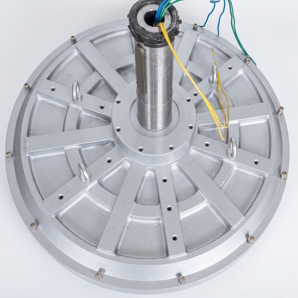
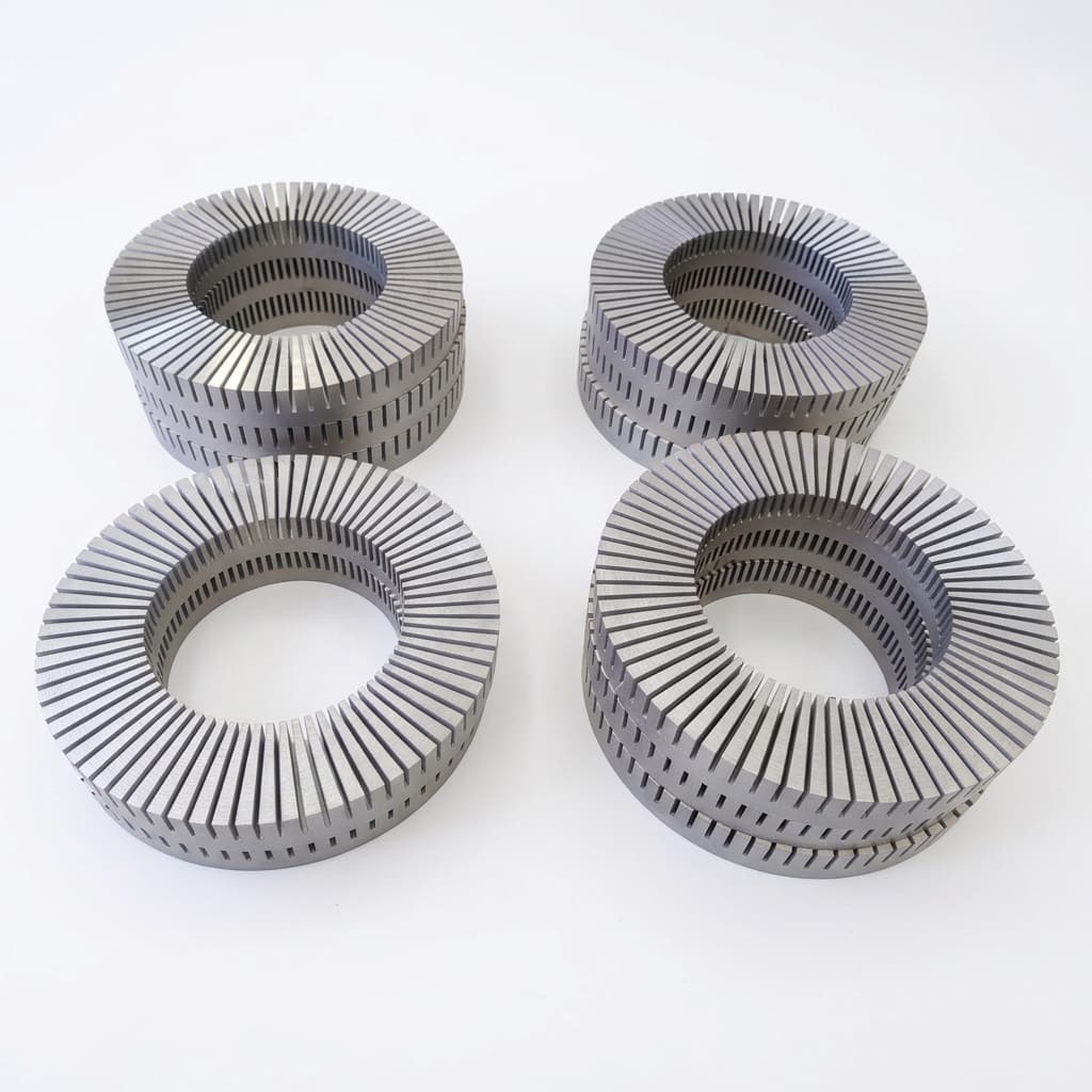
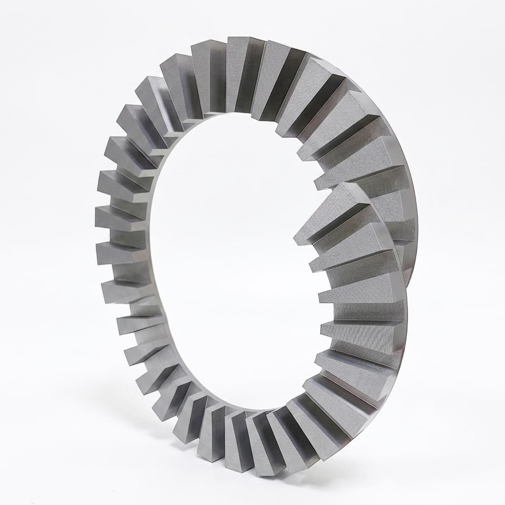
Double Stator Axial Flux Motor — view 1

Capability Highlights

  • Dual-rotor single-stator topology review for compact high-torque layouts
  • Rotor disk machining, magnet placement, balancing, and retention planning
  • Airgap fixture and bearing stack discussion for repeatable assembly
  • Thermal review for concentrated windings inside short axial packages

Typical Applications

  • Electric two-wheel traction drives
  • Compact utility vehicle drivetrains
  • Robotics rotary actuators
  • Direct-drive generator and propulsion modules

Engineering Focus

  • Rotor disk flatness, dynamic balance, magnet skew or segmentation, and retention method
  • Single stator winding layout, thermal route, impregnation, and insulation margin
  • Bearing arrangement and axial force control under temperature and speed
  • Assembly process that protects magnetized rotors and controls airgap repeatability

Key Evaluation Matrix

MetricTypical RangeWhy It Matters
Rotor balanceG2.5 to G6.3 ISO 1940-1Large-diameter disks amplify imbalance and affect noise, bearing life, and safety margin.
Airgap control0.8mm - 1.5mm mechanical gapAFPM torque and reliability are highly sensitive to disk flatness and final airgap.
Magnet retentionAdhesive, pocket, banding, or hybrid reviewRetention strategy determines speed limit, thermal durability, and production repeatability.

Buyer Decision Inputs

  • Outer diameter, stack depth, rotor disk concept, and shaft interface drawing
  • Magnet grade preference, operating temperature, and demagnetization concern
  • Peak speed, overspeed target, balance grade, and vibration acceptance plan

Factory Capability Signals

  • Rotor disk flatness, dynamic balance, magnet skew or segmentation, and retention method
  • Single stator winding layout, thermal route, impregnation, and insulation margin
  • Bearing arrangement and axial force control under temperature and speed

Validation Evidence

  • Rotor balance: Large-diameter disks amplify imbalance and affect noise, bearing life, and safety margin.
  • Airgap control: AFPM torque and reliability are highly sensitive to disk flatness and final airgap.
  • Magnet retention: Retention strategy determines speed limit, thermal durability, and production repeatability.

Standard Technical Parameters

The following physical and electrical parameters define the baseline envelope for this product family. Final values are governed by the specific winding and cooling configuration chosen during the RFQ process.

ParameterPlanning RangeNotes
Torque (Continuous / Peak)Project-specific after duty-cycle and cooling reviewPeak limits depend on inverter phase current; continuous depends on thermal path.
Motor Constant (KV)Winding dependent target set during electrical reviewAdjusted via turn count to match target bus voltage and speed.
Electrical InterfaceDC bus voltage, phase current, pole pairs, resistance, and inductance set per windingNeeded to match inverter limits, back EMF margin, and controller tuning.
Physical DimensionsProject-specific OD, axial length, shaft, and flange envelopeScalable by stator segmentation and single vs. dual-rotor topology.
Feedback / Brake OptionsHall sensors, encoder, resolver, temperature sensors, or holding brake reviewSelected against control loop bandwidth, safety behavior, and integration space.
Cooling MethodsNatural Air, Forced Air, Liquid Jacket, OilSelection determines continuous power rating and environmental sealing.
Mass / Rotor InertiaProject-specific after rotor disk, magnet carrier, shaft, and housing freezeRequired for acceleration estimates, balancing scope, and mechanical safety review.
IP RatingProject-specific IP target after housing and seal reviewAir-cooled and liquid or oil-cooled packages require different sealing validation.

RFQ Checklist

  1. Outer diameter, stack depth, rotor disk concept, and shaft interface drawing
  2. Magnet grade preference, operating temperature, and demagnetization concern
  3. Peak speed, overspeed target, balance grade, and vibration acceptance plan
  4. Cooling route, housing material, and IP or environmental requirement
  5. Prototype quantity, pilot lot expectation, and drawing ownership status

Risk Controls

  • Rotor attraction force creates unsafe assembly handling: Define magnetization sequence, fixtures, spacers, and controlled assembly steps before prototype build.
  • Thermal bottleneck reduces continuous power: Review winding fill, potting, housing contact, and cooling path with duty-cycle test points.

Production and QC Checkpoints

Use these checkpoints to turn a product-family discussion into a controlled sample and pilot-lot plan. The exact record set depends on the drawing, winding, rotor, cooling, and acceptance scope.

StageControl PointBuyer Evidence
RFQ freezeOuter diameter, stack depth, rotor disk concept, and shaft interface drawing; Magnet grade preference, operating temperature, and demagnetization concernRevisioned RFQ, package envelope, torque-speed target, and CTQ list.
Manufacturing prepRotor disk flatness, dynamic balance, magnet skew or segmentation, and retention method; Single stator winding layout, thermal route, impregnation, and insulation marginMaterial route, winding target, rotor or magnet retention method, and fixture plan.
Sample validationRotor balance, Airgap controlResistance, hipot, no-load/back EMF, runout, balance, torque-speed, or thermal records as applicable.
Pilot handoffRotor attraction force creates unsafe assembly handling; Thermal bottleneck reduces continuous powerLot traceability, change record, packaging approval, and outgoing inspection rhythm.

Engineering Asset Requests

Baseline parameter matrices, STEP files, and PDF datasheets may be shared after RFQ context is confirmed. Torque-speed maps and back EMF charts depend on the selected winding, cooling path, and validation scope.
Request 3D CAD (.STEP)Request Test Report / Data Sheet

Product Gallery

Double Stator Axial Flux Motor — view 2
Double Stator Axial Flux Motor — view 3
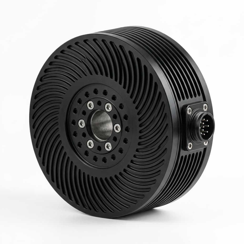
High-Torque Axial Flux Motor — view 1
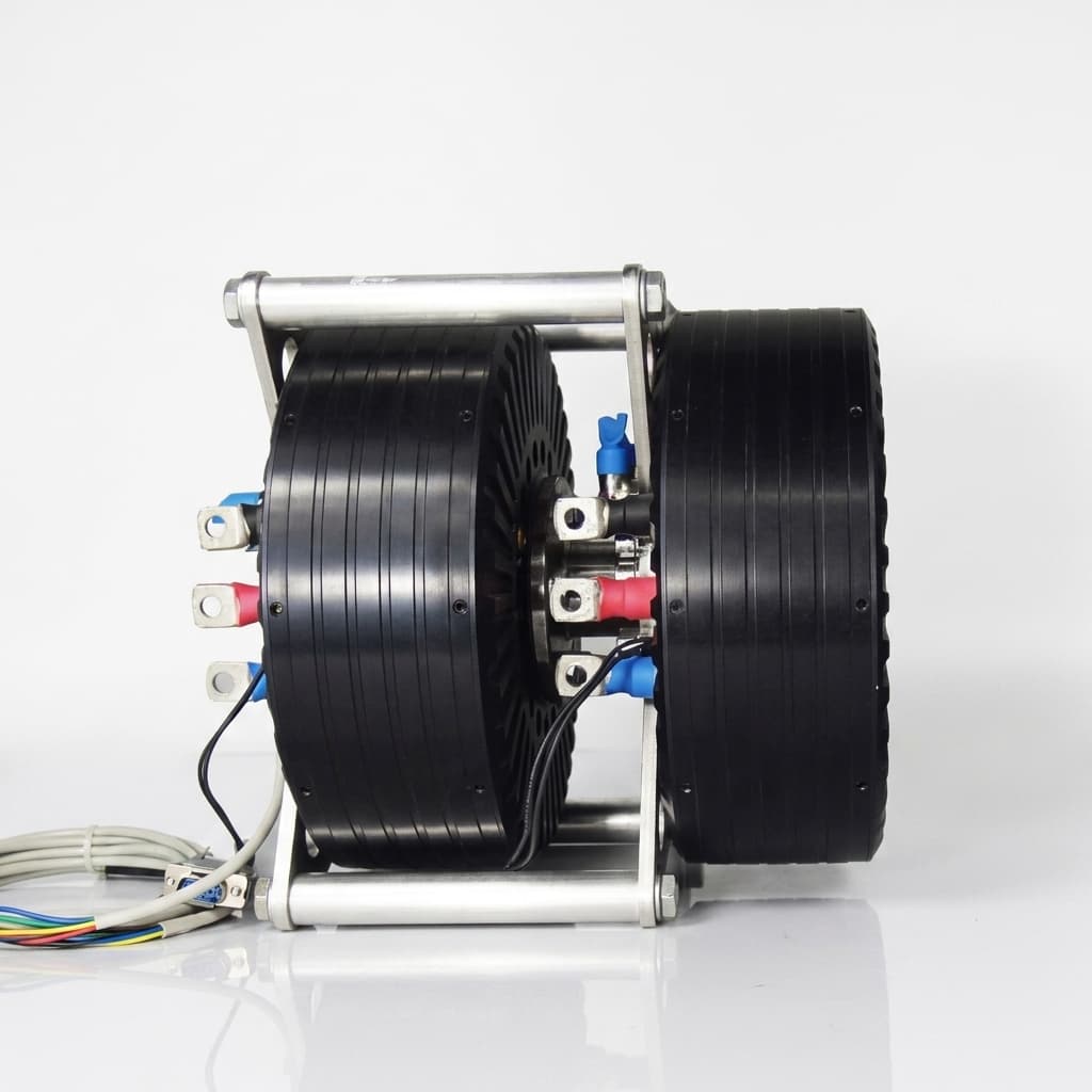
15kW 1000RPM Coreless Maglev Motor — view 1
100kW Industrial Axial Flux Motor — view 2

Buyer FAQ

Can dual-rotor AFPM be used as a direct-drive solution?

Often yes for low-speed high-torque systems, but gear elimination depends on speed, torque ripple, inverter limits, and cooling.

Do you support magnetized rotor assembly?

Yes. RFQs should specify whether magnets arrive magnetized, post-assembly magnetization is required, and what handling fixtures are expected.

Related Resources

  • AFPM Motor OEM Manufacturing
  • Rotor Magnet Assembly
  • Contact / RFQ

Inquiry Email

[email protected]

Open RFQ Email

Please include application, peak/continuous torque, speed range, voltage/current limit, outer diameter, axial length, cooling method, quantity, and drawings or reference samples.

Instant Chat

+86 188 5797 1991

Chat on WhatsApp

Share torque-speed, package, cooling, and sample quantity in the first message.