
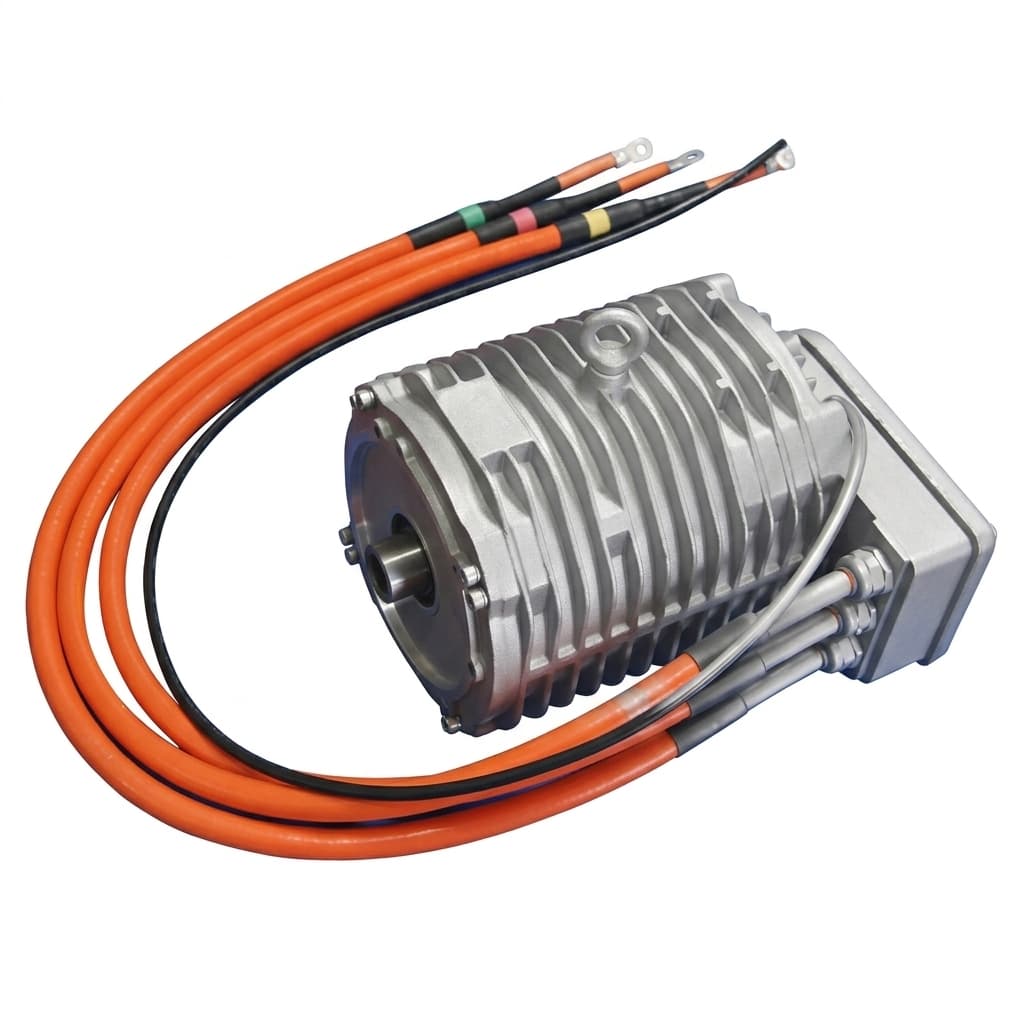
Axial Flux vs. Radial Flux Motors: A Detailed Engineering Comparison
An engineering analysis of the technical differences, torque density advantages, magnetic flux paths, and manufacturing tradeoffs between axial flux and radial flux permanent magnet motors.
When specifying electric drive systems for high-performance electric vehicles (EVs), aerospace (eVTOL), or compact robotics, engineers are increasingly moving away from legacy architectures. The architecture decision usually centers on Axial Flux Permanent Magnet (AFPM) motors vs. Radial Flux Permanent Magnet (RFPM) motors.
While both utilize high-grade Neodymium (NdFeB) magnets to generate a rotor magnetic field, the orientation of that flux relative to the axis of rotation dictates entirely different form factors, torque densities, and manufacturing complexities. This analysis details the engineering tradeoffs for procurement and motor design teams.
Executive Summary for Engineering Teams:
Axial Flux Motors (AFPM) deliver 30-40% higher torque density and are significantly shorter axially (pancake shape), making them ideal for direct-drive robotics and in-wheel EVs. However, they are harder to cool and require specialized dual-rotor assembly. Radial Flux Motors (RFPM) are the mature, cost-effective standard for high-speed, long-cylinder applications where axial space is not strictly constrained.
1. The Geometry of Magnetic Flux
To understand the performance differences, we must look at how the electromagnetic field interacts with the stator.
Radial Flux Motors (The Traditional Cylindrical Architecture)
In an RFPM motor, the magnetic flux travels radially—outward from the rotor, across a cylindrical air gap, and into the stator teeth (perpendicular to the axis of rotation).
- Form Factor: Naturally cylindrical. The motor is typically longer in the axial direction but smaller in diameter.
- Winding Profile: Copper coils are wound longitudinally through stator slots. The "end-windings" (the loops of copper at the ends of the stator that connect the active slot conductors) generate heat and add resistance but contribute zero active torque.
Magnetic Flux Path Comparison
Axial Flux Motors (The Pancake Architecture)
In an AFPM motor, the magnetic flux travels axially—parallel to the axis of rotation. The rotor and stator are designed as parallel disks rather than nested cylinders.
- Form Factor: Naturally flat. The motor is extremely short axially but has a relatively larger outer diameter (OD).
- Winding Profile: Coils are wound flat on the stator disk. In highly optimized yokeless designs, nearly 100% of the copper length is exposed to the active magnetic flux, virtually eliminating wasted end-windings.
2. Torque Density: Why Axial Flux Wins
The most significant advantage of an AFPM motor is its superior torque density (Nm/kg or Nm/L).
Torque generation is a function of the electromagnetic shear force multiplied by the radius at which it acts ($T = F \times r$). In a radial flux motor, increasing the radius means a larger, heavier cylinder. In an axial flux motor, the active electromagnetic area increases with the square of the radius ($r^2$), meaning a slight increase in the outer diameter yields massive gains in torque output.
Dual-rotor AFPM configurations (a single stator sandwiched between two magnet rotors) double the active air gap area. The resulting power density can reach up to 30-40% higher than a comparably sized radial flux motor. This makes AFPM motors ideal for direct-drive applications (like in-wheel EV motors or direct robot joints) where heavy, lossy gearboxes must be eliminated.
3. Engineering Comparison Matrix
For procurement and system engineers, comparing the core metrics side-by-side helps clarify the sourcing decision:
| Specification Metric | Radial Flux (RFPM) | Axial Flux (AFPM) |
|---|---|---|
| Torque Density | Baseline (Standard) | High (Up to 40% higher than RFPM) |
| Form Factor | Long cylinder, small diameter | Flat "pancake", large diameter |
| End-Winding Waste | High (reduces efficiency, increases weight) | Minimal to none (especially in yokeless) |
| Cooling Difficulty | Low (easy external water jacket integration) | High (inner stator requires advanced cooling) |
| Airgap Sensitivity | Low (stiff cylindrical geometry) | High (strong axial attractive forces) |
| Manufacturing Cost | Low (mature automated winding) | Medium/High (specialized winding & assembly) |
4. Thermal Management and Copper Fill Factor
Cooling is often the bottleneck for continuous torque.
In an RFPM motor, the heat-generating stator is on the outside. A simple aluminum water jacket around the housing effectively removes heat.
In a dual-rotor AFPM motor, the stator is trapped between two spinning magnet disks. Modern AFPM projects typically solve this with direct stator liquid cooling channels, dielectric oil-assisted cooling, or other application-specific thermal paths. Because AFPM stators may use rectangular flat copper wire rather than round wire, the copper fill factor can be materially higher than in many standard radial designs. The practical limit still depends on slot geometry, insulation, potting, cooling, and validation results.
5. Manufacturing Complexity and OEM Sourcing
While the physics of axial flux are superior for torque density, manufacturing is where projects often stall.
The strong axial attractive forces between the two rotor disks demand substantial structural rigidity. If the rotor backing plate deflects beyond the allowed airgap tolerance, the magnets can crash into the stator.
Partnering with a specialized AFPM Motor OEM like AFPM Motor helps buyers review these risks before sample release. A practical RFQ should verify:
- Advanced Stator Cores: Whether thin silicon steel laminations, Soft Magnetic Composites (SMC), or another stator approach is appropriate for the frequency and loss target.
- Rotor Balancing & Retention: How the magnet grade, carrier, adhesive, banding, and dynamic balance plan are matched to speed, temperature, and safety margin.
- High-Conductivity Potting: Whether vacuum impregnation, thermally conductive resin, or another insulation process is needed to stabilize coreless or yokeless stators.
6. Common Procurement Pitfalls
When sourcing AFPM motors, teams often make the mistake of evaluating an AFPM prototype based on "holding torque" alone. While AFPMs generate massive holding torque, their continuous torque is strictly limited by the thermal dissipation of the central stator. Without a mature thermal validation plan, a high-torque AFPM motor may overheat in under 5 minutes of continuous duty. Always require continuous torque curves and VPI potting specifications in your RFQ.
Architecture Selection
If your application demands high torque in a tight axial package, and you require a direct-drive solution to reduce gearbox losses, the Axial Flux Permanent Magnet Motor is a strong candidate to evaluate. Conversely, for cost-sensitive, high-speed applications with no strict length constraints, radial flux remains a viable workhorse.
Are you evaluating an AFPM topology for your next electric drive platform? Contact our engineering team to discuss your package envelope, torque-speed curve, and OEM supply requirements.
Author

Categories
More Posts
Mercedes-Benz Launches Series Production of Axial Flux Motors: Supply Chain & Procurement Impact
Mercedes-Benz begins large-scale series production of axial flux motors in Berlin. Explore the supply chain implications, technology scaling, and strategic impact for procurement and engineers.
NdFeB Magnet Grades in Axial Flux Motors: A Cost and Temperature Specification Guide for Buyers
Use this procurement guide to compare NdFeB magnet grades for axial flux motors, SH/UH/EH temperature limits, Dy/Tb cost drivers, and supplier checks.
Quality Gate Checklist for AFPM Motor OEM Programs: From Sample to Mass Production
A comprehensive quality gate framework for OEM procurement teams managing axial flux motor programs — covering prototype acceptance, pilot validation, and mass production control plans.