
Interactive Tool + Technical Report
Axial Flux Electric Motor Selection & Sizing
Compare axial flux electric motor topology, packaging and duty requirements. Use the 10.5 kW reference calculator to explore the method, then choose a power-specific guide and request supplier evidence for your operating point.
Reference point
10.5 kW / 45 Nm
Base speed
About 2228 RPM
Primary gate
Duty cycle + cooling
100 kW path
Feasibility + evidence
Need 100 kW shaft output? Use the 100kW axial flux motor calculator and RFQ guide for torque, DC current, duty boundaries and manufacturer examples.
Executive Summary
Core Conclusions for Axial Flux Electric Motors
Use 10 kW as a sizing checkpoint, not a fixed SKU
A 10 kW axial flux motor request must still be mapped to voltage, RPM, duty cycle, cooling, inverter limits, and package space. The calculator uses a 10.5 kW / 45 Nm reference point so the visitor can see whether the point is torque-limited, power-limited, current-limited, or thermal-risk limited.
Evidence: AFPM Motor calculator model and formula table on this page.
Peak and continuous ratings must stay separated
Public axial flux benchmarks are useful for topology and comparison, but a continuous 10 kW S1 rating cannot be assumed without winding-temperature, cooling-path, mounting, and controller-current evidence.
Evidence: EMRAX benchmark context and AFPM Motor calculator limits.
Axial packaging is strongest when length is constrained
The axial flux topology routes flux along the shaft and uses a larger active radius, which can improve torque density in flat packages for drones, robotics, light EVs, and direct-drive modules.
Evidence: YASA and Evolito topology explanations, plus the encoded stack diagram.
Higher voltage is often the first current-risk lever
At the same output power, a higher DC bus lowers battery-side current in the calculator. That does not remove phase-current, inverter, fuse, connector, or thermal validation, but it makes the first screening more realistic.
Evidence: Current formula: output watts / (V x 0.95 nominal efficiency).
Do not choose axial flux only because the power is 10 kW
Radial flux motors may be simpler to source when axial length is available. Axial flux becomes compelling when diameter, torque density, direct-drive fit, or short axial package length is the gating constraint.
Evidence: Comparison and risk tables in the report layer.
100 kW requests need feasibility screening first
A 100 kW axial flux motor can be viable when short axial length, torque density, or direct-drive packaging is the gating constraint. It should not be sized from the 10.5 kW reference calculator alone; first screen DC bus voltage, cooling path, phase-current limit, rotor containment, and supplier evidence.
Evidence: Dedicated 100kW calculator, current formula, and RFQ checklist.
Architecture
Why Axial Flux Electric Motors Excel
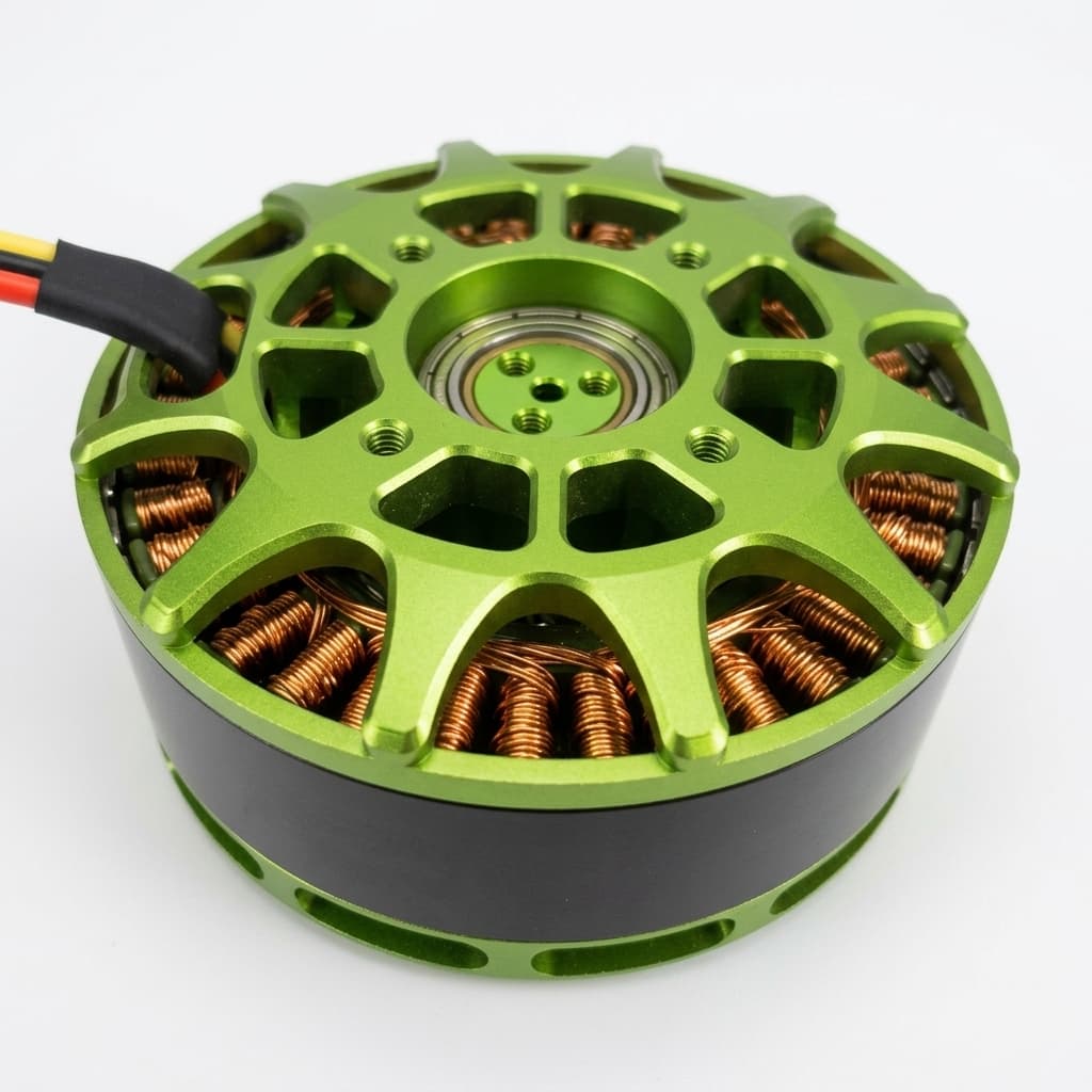
The primary advantage of an axial flux electric motor lies in its air-gap topology. By aligning the magnetic flux parallel to the axle, the active material operates at a larger radius, producing greater torque within a much shorter package length.
Method
How the 10 kW Calculator Makes Its Call
The tool provides a deterministic screening result. It is useful before RFQ, but it deliberately stops short of claiming final dyno, inverter, or thermal validation.
| Check | Formula | Decision Use | Limit |
|---|---|---|---|
| Torque-speed power check | kW = Nm x RPM / 9549 | Shows whether the requested speed can reach 10 kW before the 45 Nm torque ceiling is hit. | Uses shaft output power only; it is not a thermal guarantee. |
| Post-base-speed torque check | Nm = kW x 9549 / RPM | Shows available shaft torque after the 10.5 kW power ceiling is reached. | Mechanical rotor speed, balance, bearings, and containment still need review. |
| Battery-side current screen | A = output watts / (V x 0.95) | Flags inverter, cable, connector, fuse, and battery pressure before RFQ. | Uses nominal efficiency and does not replace phase-current or transient validation. |
| Thermal boundary screen | Flag near 90% power, 98% torque, high RPM, or high current | Separates short peak use from operating points that need cooling evidence. | Final S1 power needs dyno and winding-temperature data. |
Scenario Outputs
Example 10 kW-Class Operating Points
These examples use the same formulas as the calculator and are shown to make the result interpretation reproducible.
| Application | Input | Model Output | Decision | Caveat |
|---|---|---|---|---|
| Heavy-lift UAV | 96 V, 2000 RPM | About 9.4 kW, 45.0 Nm, 103 A | Promising for takeoff and climb screening. | Hover power, propeller airflow, and winding temperature still decide continuous margin. |
| Light EV / motorcycle | 96 V, 3000 RPM | 10.5 kW, about 33.4 Nm, 115 A | Good first-pass acceleration point. | Road-load duration, gearing, gradeability, and liquid/air cooling decide whether it can be sustained. |
| Commercial karting | 48 V, 2200 RPM | About 10.4 kW, 45.0 Nm, 227 A | Feasible as a burst benchmark, but current is the main boundary. | Controller current type, cable sizing, session length, and cooldown time must be specified. |
| Industrial robotics | 72 V, 1200 RPM | About 5.7 kW, 45.0 Nm, 83 A | Torque-limited point useful for compact direct-drive joints. | Repeated hold torque or stall duty can exceed the compact frame thermal path. |
| Automotive EV traction & VTOL (100 kW class) | 400 V - 800 V, 4000-8000 RPM | Current screen: about 263 A at 400 V or 132 A at 800 V. Torque screen: about 239 Nm at 4000 RPM or 119 Nm at 8000 RPM. | Use the dedicated 100kW guide before a supplier shortlist; the 10.5 kW calculator is method reference only. | Final feasibility depends on measured thermal data, inverter phase current, rotor containment, and duty-cycle proof. |
Boundaries and Risks
Where the Tool Result Can Mislead
A valid calculator result is only a first screening pass. Use the triggers below to decide what evidence to request before design lock.
Confusing peak 10 kW with continuous S1 power
Trigger: Long duty cycle, marine cruise, road-load hold, or repeated starts
Impact: Overheated windings, controller derating, or failed prototype test
Mitigation: Ask for S1 output at ambient temperature, mounting condition, cooling method, and winding temperature limit.
Low-voltage current overload
Trigger: 48 V or lower bus while targeting near 10 kW output
Impact: Large cables, connector heat, fuse stress, and inverter oversizing
Mitigation: Raise bus voltage where the system allows, then verify battery current and phase-current limits separately.
Topology mismatch
Trigger: Application has spare axial length and needs the lowest sourcing risk
Impact: Unnecessary custom cost versus a mature radial-flux package
Mitigation: Use axial flux only when flat package length, torque density, or direct-drive integration is a gating requirement.
Evidence gap in public references
Trigger: Supplier pages publish topology benefits but omit exact duty cycle data
Impact: Wrong weight, efficiency, cooling, or continuous-power assumption
Mitigation: Treat public benchmarks as context and request drawings, efficiency map, thermal report, and controller data before design lock.
Manufacturing scaling for 100 kW class
Trigger: Moving from 10 kW prototype to 100 kW mass production
Impact: Cost overruns from strict air-gap control, rotor containment, thermal-path validation, magnet sourcing, and automated inspection requirements.
Mitigation: Involve manufacturing engineers early; verify the supplier has mature, automated processes for the specific axial stator core and magnet assembly.
Comparison
Axial Flux vs Alternatives for a 10 kW Request
The main keyword stays axial flux electric motor, but the decision often comes down to whether a flat package actually changes the integration outcome.
| Dimension | Axial Flux Fit | Alternative | Decision Rule |
|---|---|---|---|
| Package constraint | Best when the motor must be short along the shaft | Radial flux is simpler if axial length is available | Choose axial flux when flat form factor is a hard constraint. |
| 10 kW current pressure | Similar electrical current math; packaging may be smaller | Radial flux may offer more off-the-shelf inverter pairings | Use the calculator to set bus voltage and current before comparing suppliers. |
| Thermal path | Needs clear stator heat path in compact packages | Radial flux housings may have mature cooling references | Require measured thermal data for either topology when duty is continuous. |
| Prototype risk | Higher value when custom geometry unlocks the application | Lower sourcing risk for standard industrial layouts | Pick axial flux when the integration gain justifies custom validation. |
| 100 kW thermal management | Requires documented heat removal from the stator, winding temperature evidence, and usually liquid or direct-stator cooling for continuous duty. | Radial flux water-jacket cooling is highly mature and often sufficient for 100 kW. | Only specify a 100 kW axial flux motor if the packaging or torque-density gain justifies extra thermal and mechanical validation. |
Validation Sources
References and Limits
Information regarding the 10 kW axial flux motor intent is tied to traceable source rows and explicit limits. Unknowns stay visible until a supplier drawing, dyno test, and thermal report are available.
Reviewed by AFPM Motor engineering team on September 23, 2026
Scope: electromagnetic topology, first-pass motor sizing, RFQ evidence requirements, and public-source limitations. Final production selection still requires supplier drawings, dyno data, and thermal validation.
| Source | Context | Limitation |
|---|---|---|
| AFPM Motor 10.5 kW Calculator Model Reviewed: September 23, 2026 | Provides the mathematical basis for the 10 kW axial flux motor sizing, torque, and speed predictions. | Mathematical screen only; actual dyno testing is required for production. |
| AFPM Motor 100mm Generator Sizing Tool Reviewed: September 23, 2026 | Provides performance estimation for a 100mm diameter axial flux generator constraint. | Initial sizing estimation based on cooling methods. |
| EMRAX official motor data Reviewed: September 23, 2026 | Comparable AFPM product-class benchmark for separating peak, continuous, voltage, cooling, and efficiency-map expectations. | Competitor motor family, not this 10 kW request; use as context only. |
| Evolito Axial-Flux Technology Reviewed: September 23, 2026 | Supports aviation use cases where high torque density from an axial flux electric motor is critical. | Reference architecture, not a specific 10 kW datasheet. |
| YASA Technology Guide Reviewed: September 23, 2026 | Explains the topology benefits of axial flux electric motors compared to radial flux. | General topology context. |
| BIZ Karts EcoVolt GT product page Reviewed: September 23, 2026 | Commercial reference for a listed 10.5 kW / 45 Nm permanent magnet brushless motor and 48 V controller class. | Not an AFPM Motor datasheet and not proof of axial flux topology, continuous rating, or cooling margin. |
| AFPM Motor 100 kW feasibility screen Reviewed: September 23, 2026 | Provides a dedicated 100kW operating-point calculator, manufacturer evidence and RFQ requirements. | First-pass engineering screen only; a final 100 kW selection still needs torque-speed curves, thermal test data, inverter limits, drawings, and production tolerance evidence. |
FAQ
Axial Flux Electric Motor FAQ
Understanding Axial Flux Electric Motors
- What makes an axial flux electric motor different?
- Unlike radial flux motors where magnetic flux moves radially across the air gap, an axial flux electric motor routes flux parallel to the shaft. This allows a pancake-like form factor and a larger active radius, which is why it is often considered for short-package, high-torque systems.
- Is a 10 kW axial flux motor suitable for electric vehicles?
- It can be suitable for light EVs, motorcycles, compact utility vehicles, and karts, but only after separating peak acceleration power from continuous road-load power. Use the calculator to screen voltage, RPM, and current, then request thermal and controller data.
- How do I cool an axial flux electric motor?
- Cooling depends on duty cycle and package geometry. Short burst use may work with airflow or forced air, while continuous 10 kW duty needs a verified stator heat path, winding temperature limit, mounting condition, and often liquid cooling or a defined cold plate.
- Is there a 100 kW axial flux motor?
- Manufacturer ratings exist in this power class, but continuous output depends on the configuration and cooling boundary. Use our dedicated 100kW guide for the operating-point calculation and published examples, then request supplier torque-speed and thermal evidence.
Sizing and Specifications
- Why does the calculator use 10.5 kW and 45 Nm?
- It is a practical 10 kW-class benchmark that lets engineers test voltage, RPM, current, torque, and thermal boundaries before ordering a prototype.
- Does higher voltage improve the motor?
- For a target 10 kW axial flux motor, higher voltage reduces the required current. This lowers I2R heat losses in cables and eases inverter requirements.
- Why does 45 Nm not always equal 10 kW?
- Power depends on torque and speed. At 45 Nm, 10.5 kW occurs at about 2228 RPM. Below that speed the motor is torque-limited; above that speed the power ceiling reduces available torque.
- What should I send with a 10kw axial flux motor RFQ?
- Send target power, continuous and peak duration, DC bus voltage, shaft RPM, torque or load curve, cooling method, package envelope, controller limits, encoder needs, and prototype quantity.
Risk and Selection
- When should I not use an axial flux motor?
- Avoid forcing axial flux when axial length is not constrained, when a standard radial motor already fits, or when the program cannot support custom thermal, mechanical, and inverter validation.
- Can I assume public axial flux benchmarks apply to my design?
- No. Public benchmarks are useful for topology and market context, but final weight, efficiency, S1 rating, temperature rise, and lifetime depend on the exact winding, housing, cooling, inverter, and duty cycle.
- What is the minimum validation package before production?
- Request a drawing, torque-speed curve, efficiency map, winding temperature test, cooling condition, insulation data, balance requirement, controller limits, and inspection plan before locking production geometry.