
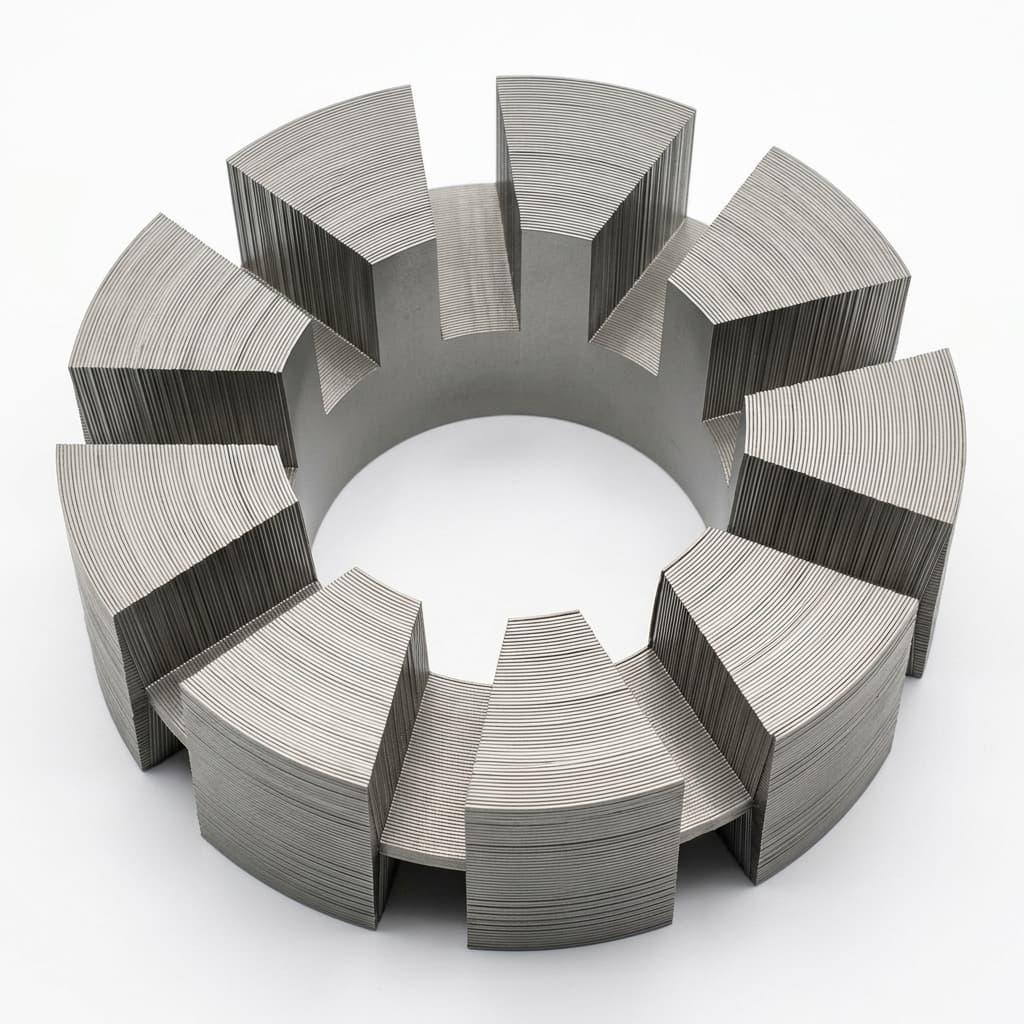
Flat Wire vs. Round Wire Winding in AFPM Stators: Impact on Efficiency and Manufacturing
A quantitative analysis of flat (rectangular) copper wire versus round wire winding techniques in axial flux motors, covering fill factor, thermal performance, manufacturing cost, and OEM sourcing implications.
The stator winding is the single most performance-critical manufacturing step in an axial flux permanent magnet motor. The choice between flat (rectangular) wire and traditional round wire affects copper fill factor, thermal resistance, AC losses, manufacturing complexity, and ultimately—the motor's real-world efficiency and continuous power output.
For OEM procurement teams evaluating AFPM motor suppliers, understanding the winding technology behind a quoted efficiency number is essential for making informed sourcing decisions.
Executive Summary for Engineering Teams:
Flat wire achieves 65-80% copper fill factor (vs. 40-55% for round wire), delivering 10-20% lower copper losses (I²R) and significantly better thermal conductivity from winding to housing. However, flat wire requires CNC-controlled precision forming equipment and carries 2-3× higher per-unit winding cost. It is justified for motors above 5 kW continuous or applications where thermal headroom is critical.
1. Copper Fill Factor: The Foundation of Motor Efficiency
Copper fill factor (also called slot fill or packing density) measures how much of the stator's available winding space is actually occupied by copper versus air gaps and insulation.
In a stator slot or coil cavity, every cubic millimeter that is not copper is either air (a poor thermal conductor) or insulation (necessary but thermally resistive). Higher fill factor means:
- More copper in the same volume → lower resistance → lower I²R losses
- Better thermal contact between conductors → more effective heat transfer to the housing
- Higher continuous power for the same motor frame size
| Winding Type | Typical Fill Factor | Air Gap Between Conductors |
|---|---|---|
| Round wire (random wound) | 40-50% | High — circular cross-sections stack inefficiently |
| Round wire (precision wound) | 50-55% | Moderate — controlled layering reduces voids |
| Flat wire (hairpin) | 65-75% | Low — rectangular sections tessellate tightly |
| Flat wire (continuous bar) | 70-80% | Minimal — pre-formed bars fill slots precisely |
Cross-Section View: Round vs. Flat Wire Packing
2. Thermal Performance: The Hidden Advantage
Higher fill factor doesn't just reduce electrical losses — it fundamentally improves thermal performance. With flat wire:
- Copper conductors make surface-to-surface contact instead of point-to-point (round wire touching at tangent points)
- The thermal resistance from the innermost conductor to the outer housing drops by 30-50%
- Flat surfaces against the stator back-iron or cooling channel provide superior heat transfer
This thermal advantage is especially critical in dual-rotor AFPM motors where the stator is sandwiched between two rotors and heat extraction is the continuous power bottleneck. A flat-wire AFPM motor can sustain 15-25% higher continuous power than a round-wire motor of identical outer dimensions.
3. AC Losses: Where Flat Wire Has a Disadvantage
At high electrical frequencies (high pole count × high RPM), alternating current induces skin effect and proximity effect losses in the conductors. These AC losses are proportional to the conductor cross-sectional area.
Because flat wire has a larger individual conductor cross-section than fine round wire, it is more susceptible to AC losses at high frequencies. This is why:
- High-speed AFPM motors (over 10,000 RPM) may still use Litz wire (bundles of very fine round wires individually insulated) to minimize skin effect
- Medium-speed motors (1,000-6,000 RPM) often segment the flat wire into 2-4 parallel conductors to reduce effective cross-section while maintaining fill factor
- Low-speed direct-drive motors (under 1,000 RPM) benefit enormously from flat wire with negligible AC loss penalty
Selection Guide by Operating Speed
- 0-1,000 RPM (direct-drive AGV, generator): Flat wire — maximum fill factor, minimal AC losses
- 1,000-6,000 RPM (EV traction, industrial): Flat wire with parallel segmentation, or precision-wound round wire
- 6,000-20,000 RPM (high-speed spindle, aerospace): Litz wire — many fine strands minimize skin/proximity effect
4. Manufacturing Cost Comparison
| Cost Factor | Round Wire | Flat Wire |
|---|---|---|
| Raw material | Standard enameled copper (commodity) | Precision rectangular magnet wire (specialty) |
| Winding equipment | Standard winding machine ($5K-20K) | CNC bending/forming machine ($50K-200K) |
| Labor per stator | 15-30 min (automated or semi-auto) | 30-60 min (precision forming + insertion) |
| Tooling per variant | Minimal (adjust turns count) | Moderate (new forming dies per geometry) |
| Unit cost impact | Baseline | +40-80% on winding assembly cost |
| MOQ sensitivity | Low | Medium (tooling amortization matters) |
For OEM manufacturing programs with annual volumes above 500-1,000 units, the per-unit cost premium of flat wire drops significantly as tooling costs are amortized.
5. What to Specify in Your RFQ
When requesting quotes for AFPM motors, explicitly ask:
- What is the measured copper fill factor? (Not theoretical — measured from a cross-section photo)
- What wire type is used? (Round, precision-wound round, flat bar, hairpin, Litz)
- What is the continuous power at Class H (180°C) winding temperature?
- Can you provide a back-to-back efficiency comparison between your round-wire and flat-wire builds for the same frame size?
- What is the winding insulation process? (Dip-and-bake, trickle varnish, or full Vacuum Pressure Impregnation)
The best AFPM motor suppliers will have cross-section photographs of their stators readily available, showing actual fill factor. If a supplier cannot provide this, their quoted efficiency numbers should be treated with caution.
Ready to compare winding options for your axial flux motor project? Contact our engineering team with your power, speed, and thermal requirements for a technology recommendation.
Author

Categories
More Posts

Specifying Axial Flux Motors for 800V Architectures: Insulation & PD Risks
Learn how to specify 800V axial flux motors for SiC inverters: PDIV limits, VPI checks, insulation classes, and RFQ evidence to request from suppliers.
Quality Gate Checklist for AFPM Motor OEM Programs: From Sample to Mass Production
A comprehensive quality gate framework for OEM procurement teams managing axial flux motor programs — covering prototype acceptance, pilot validation, and mass production control plans.
Sourcing Dual-Rotor Axial Flux Motors: An OEM Buyer's Guide
An engineering guide for procurement and engineering teams on how to specify, validate, and source dual-rotor AFPM motors from reliable OEM manufacturing partners.