
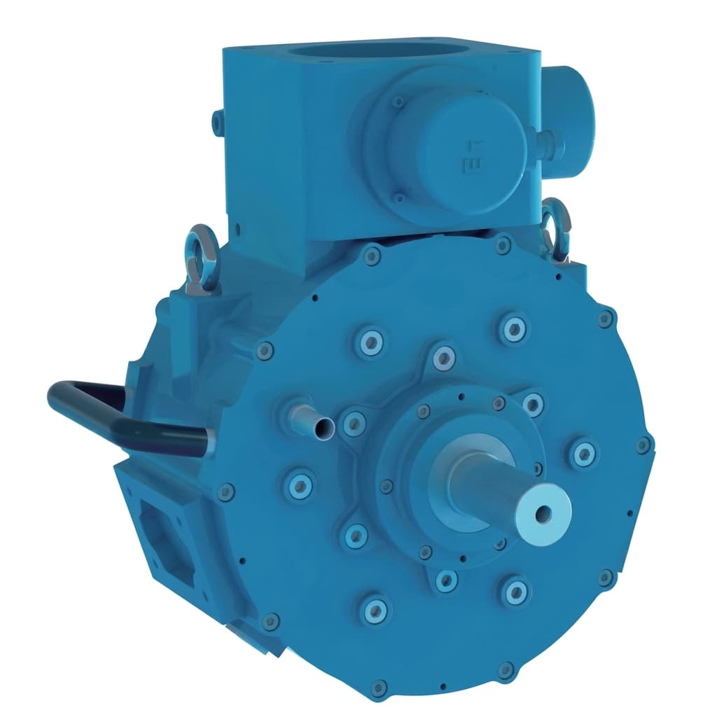
Liquid Cooling vs. Forced Air for AFPM Motors: Thermal Engineering Guide
A practical thermal management comparison for OEM buyers specifying cooling systems for axial flux permanent magnet motors in continuous-duty industrial applications.
Thermal management is often the single largest constraint on continuous power output in axial flux permanent magnet (AFPM) motors. While peak torque specifications attract attention, continuous torque—the output the motor can sustain indefinitely without thermal degradation—is what determines real-world system performance.
For procurement and engineering teams evaluating AFPM motor solutions, choosing between liquid cooling and forced-air cooling is not simply a preference—it is a fundamental architecture decision that affects motor size, weight, cost, reliability, and continuous power density.
Executive Summary for Engineering Teams:
Forced-air cooling is simpler, lighter, and cheaper, but limits continuous power to roughly 50-60% of peak capacity. Liquid cooling (water-glycol or oil) can sustain 80-95% of peak power continuously, but adds system complexity (pump, radiator, fluid lines, leak risk). The right choice depends entirely on your duty cycle: intermittent burst applications favor air cooling; continuous-duty industrial loads demand liquid cooling.
1. Why Thermal Management Matters More in AFPM Motors
In a dual-rotor AFPM motor, the stator—where nearly all heat is generated from copper losses (I²R)—is sandwiched between two spinning rotor disks. Unlike radial flux motors where the stator is on the outside with direct access to a cooling jacket, the AFPM stator has minimal exposed surface area for heat rejection.
This fundamental geometric challenge means that an AFPM motor rated for 20 kW peak power may only deliver 8-12 kW continuously under natural convection. The thermal path from the copper windings to ambient air is the bottleneck, not the electromagnetic design.
Thermal Path Comparison: Air vs. Liquid Cooling
2. Forced-Air Cooling: When Simplicity Wins
Forced-air cooling uses fans (internal centrifugal or external blower) to push air across the motor's outer housing fins or through internal ventilation channels.
Best suited for:
- Intermittent duty cycles (S2/S3): Applications where the motor operates at peak power for short bursts with rest periods—drones, robotics pick-and-place, racing vehicles
- Weight-sensitive platforms: No additional coolant loop weight
- Low-maintenance environments: No fluid leaks, no pump failure modes
Engineering limits:
- Continuous power is typically capped at 50-65% of peak due to limited convective heat transfer coefficient (h ≈ 25-100 W/m²K for forced air)
- Performance degrades significantly at high ambient temperatures (>40°C)
- Acoustic noise from high-CFM fans can be problematic in robotic joint drives
3. Liquid Cooling: When Continuous Power is Non-Negotiable
Liquid cooling circulates water-glycol (or dielectric oil) through channels machined into the motor housing or integrated directly into the stator assembly.
Best suited for:
- Continuous duty (S1): Industrial drives, EV traction motors, generators under constant load
- High power density requirements: Sustained output at 80-95% of peak rating
- Harsh environments: Sealed IP67 housings where external airflow is unavailable
Engineering considerations:
- Requires external infrastructure: pump, radiator/heat exchanger, reservoir, fluid lines
- Adds 2-5 kg of system weight and $150-400 in BOM cost
- Introduces leak risk—critical in aerospace and marine applications
- Convective heat transfer coefficient jumps to h ≈ 3,000-10,000 W/m²K
4. Performance Comparison Matrix
For procurement teams building an RFQ comparison, these are the quantitative metrics to request from your AFPM motor supplier:
| Specification | Forced-Air Cooled | Liquid Cooled |
|---|---|---|
| Continuous / Peak Power Ratio | 50-65% | 80-95% |
| Heat Transfer Coefficient | 25-100 W/m²K | 3,000-10,000 W/m²K |
| Max Winding Temperature Rise | 80-120°C above ambient | 20-40°C above ambient |
| System Weight Penalty | None | +2-5 kg (pump, radiator, fluid) |
| System Cost Adder | None | +$150-400 |
| IP Protection Achievable | IP44-IP55 | IP65-IP67 |
| Maintenance | Fan replacement only | Coolant change, leak inspection |
| Acoustic Noise | Medium-High (fan noise) | Low (pump only) |
5. Hybrid Approaches: Oil-Mist and Stator-Direct Cooling
Advanced OEM manufacturing programs now offer hybrid thermal solutions that blur the boundary between air and liquid cooling:
-
Dielectric oil flooding: The entire stator cavity is flooded with a non-conductive oil (e.g., Novec or mineral oil). The oil absorbs heat directly from the copper windings and is pumped to an external oil-air heat exchanger. This eliminates the need for precision-machined coolant channels and provides excellent thermal uniformity.
-
Stator-embedded cooling tubes: Copper or stainless steel cooling tubes are potted directly into the stator epoxy during vacuum impregnation. Coolant flows through tubes that are in direct thermal contact with the windings—the shortest possible thermal path.
-
Phase-change materials (PCM): For burst-duty applications, PCM pouches embedded in the housing absorb thermal spikes and slowly release heat during rest cycles, effectively extending the burst window without adding a coolant loop.
Buyer's RFQ Checklist: Thermal Management
- What is the maximum continuous power output at 40°C ambient, and what is the assumed cooling method?
- Can you provide a thermal derating curve showing continuous power vs. ambient temperature?
- What is the stator winding insulation class (Class F = 155°C, Class H = 180°C, Class N = 200°C)?
- For liquid-cooled variants, what are the coolant flow rate (L/min) and inlet temperature requirements?
- Has the motor been validated on a dynamometer under S1 continuous duty for the rated thermal life?
Making the Right Choice
The cooling decision is ultimately driven by your application's duty cycle. If your motor operates at peak power for less than 30% of the time, forced-air cooling is likely sufficient and avoids unnecessary system complexity. If your application demands sustained high-power output—such as industrial pumps, CNC spindles, or electric vehicle traction—liquid cooling is the only reliable path.
When requesting quotes from AFPM motor suppliers, always specify your actual duty cycle (S1/S2/S3/S6) and ambient temperature range. A motor datasheet that only shows peak power without a thermal derating curve is hiding critical information.
Need help selecting the right thermal configuration for your project? Contact our engineering team with your duty cycle and environmental requirements, and we'll provide a thermal simulation-backed recommendation.
Author

Categories
More Posts
Mercedes-Benz Launches Series Production of Axial Flux Motors: Supply Chain & Procurement Impact
Mercedes-Benz begins large-scale series production of axial flux motors in Berlin. Explore the supply chain implications, technology scaling, and strategic impact for procurement and engineers.
Quality Gate Checklist for AFPM Motor OEM Programs: From Sample to Mass Production
A comprehensive quality gate framework for OEM procurement teams managing axial flux motor programs — covering prototype acceptance, pilot validation, and mass production control plans.
Why Coreless Axial Flux Generators are Dominating Light Renewable Energy
Discover why coreless maglev AFPM generators are becoming the gold standard for vertical axis wind turbines (VAWT), micro-hydro, and low-RPM energy capture.