
10kW motor sizing
10kW Axial Flux Motor Calculator
Estimate torque, speed and DC current at 10kW shaft output. Then check the supplier evidence needed for your duty and cooling.
By AFPM Motor, operated by Magatom Dynamics Co., Ltd.. Published . Reviewed
Use the calculatorDecision summary
10kW Integration Realities
A 10kW rating requires careful integration planning around bus voltage, DC bus current, phase current limits, and thermal management.
Treat 10kW as a duty-cycle claim
Ask whether 10kW is continuous, short-time or intermittent output, and request load duration, rest periods and ambient/cooling conditions. A power label alone does not define thermal capability.
Continuous operation needs thermal proof
For a sealed hub, marine pod or industrial pump, request steady-state winding temperatures at the actual load and ambient conditions. Air or liquid cooling can only be accepted against that evidence.
Estimate DC current before comparing packs
At 10kW shaft output and 94% assumed combined efficiency, current is about 222A at 48V, 111A at 96V, 74A at 144V and 27A at 400V. These are nominal screening values, not cable or battery ratings.
Compare complete packages on the same basis
A verified 10kW mass range is not established by the sources on this page. Request motor, inverter and cooling-system masses separately, with peak/continuous ratings and the efficiency test point.
Diameter is one design variable, not a verdict
An idealized axial-flux torque comparison uses D³; the radial expression also depends on axial length (D²L). The comparison assumes comparable loading and geometry ratios, so it does not prove that axial flux always wins at 10kW.
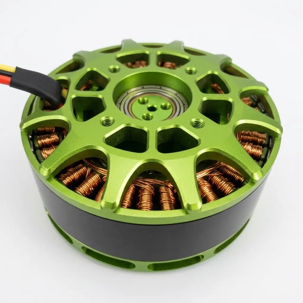
System boundary
Duty, cooling and voltage tradeoffs
The difference between a 10kW peak motor and a 10kW continuous motor depends on the verified duty cycle, coolant conditions, and thermal dissipation path.
S1: sustained load to thermal equilibrium. S2: a specified run followed by cooling. S3: repeating load/rest cycles with insignificant starting losses. These duty types do not by themselves specify a peak power. Duty definitions.
Calculated at 10kW shaft output and 94% combined DC-to-shaft efficiency; excludes auxiliaries. Values are estimates, not current ratings.
| Architecture | Estimated DC Bus Current | Cable / DC-Link Impact | Integration Note |
|---|---|---|---|
| 48V DC | ~222A | Highest current in this comparison | Validate pack sag, DC conductors, connectors and inverter temperature. |
| 96V DC | ~111A | Half the 48V current | Check actual pack voltage range and DC/phase limits independently. |
| 144V DC | ~74A | One-third of the 48V current | Confirm winding, inverter and insulation compatibility. |
| 400V DC | ~27A | Lower current, higher voltage | Confirm insulation coordination and the full drive voltage rating. |
Calculation method and limits
What the estimate can establish
1. Mechanical requirement
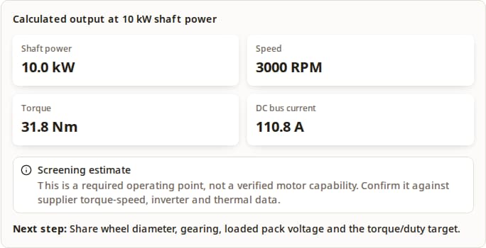
P = T × ω, with ω = 2π × RPM / 60. For kW and Nm, T ≈ 9549.3 × P / RPM. At 3,000 RPM, 10kW requires 31.8 Nm.
2. Electrical assumption
I ≈ 10,000 / (Vdc × 0.94). The assumed 94% includes motor and inverter losses. At 96V, changing this assumption from 90% to 96% gives about 116A to 109A; this is sensitivity, not a verified efficiency range.
3. Supplier verification
Unknown: winding constants, phase RMS current, efficiency map, base speed, peak duration and continuous thermal capability. The tool cannot determine motor feasibility, mass, price or certification.
The 500–10,000 RPM window and review triggers above 200A, 8,000 RPM or 120 Nm are editorial screening prompts. They are not a supplier operating envelope. Torque mode can produce a speed outside that window and explicitly requests a custom review. See back-EMF limitations and rating-standard scope.
Request a 10kW duty and cooling reviewCompare alternatives before requesting a quote
| Decision | Axial-flux candidate | Radial-flux alternative |
|---|---|---|
| Short axial space; diameter available | Consider disc packaging; verify air-gap stiffness and bearing loads. | Compare a shorter stack or a geared arrangement against the same envelope. |
| Purchase and installation cost | Quote custom tooling, inverter, cooling, validation and minimum quantity. | Request a standard-frame alternative; compare complete installed cost. |
| Continuous industrial load | Accept only a thermal test at the required speed and cooling conditions. | Use the same duty and ambient basis; an existing validated drive may reduce integration work. |
| Price, lead time and service life | Unknown for this requirement until quoted and validated. | Also unknown until a specific package and support plan are compared. |
Procurement checklist, not a measured ranking. Compare quotations on the same duty, installation and validation basis to avoid tooling or cooling costs erasing a packaging benefit.
Evidence and method
Method, worked examples and integration risks
Use calculated scenarios and supplier evidence requests to review your powertrain. The examples below are not measured deployments.
RFQ Evidence Checklist
| Spec Area | Ask For | Decision Value |
|---|---|---|
| Rating basis | Continuous S1 kW, peak kW, S2 run time or S3 duty factor, rest period, and ambient temperature | Separates true 10kW continuous packages from short-burst traction ratings. |
| Cooling circuit | Coolant type, flow rate, pressure drop, max winding temperature, and sensor placement | Shows whether 10kW can be sustained without thermal derating. |
| Electrical interface | DC link range, inverter phase RMS/peak current, connector type, and cable size | Prevents DC bus current from being confused with motor phase current. |
| Torque-speed map | Peak and continuous torque curves, base speed, efficiency map, and field-weakening limit | Confirms whether your operating point stays inside the efficient envelope. |
| Mechanical package | Motor mass, outside diameter, axial length, shaft loads, bearing rating, and IP rating | Validates packaging, power density, and axial-load risk together. |
Worked Screening Examples
Assume 10kW shaft output and 94% combined efficiency. Select the matching application example in the calculator to reproduce each row; then request the evidence in the RFQ note.
| Application | DC Voltage | Speed | Torque | DC Current | RFQ Note |
|---|---|---|---|---|---|
| Light EV / go-kart | 96V DC | 3,000 rpm | 31.8 Nm | ~111A | Good first screening case when pack current, connector rating, and burst duration are explicit. |
| Electric motorcycle | 144V DC | 5,000 rpm | 19.1 Nm | ~74A | Lower DC current than 96V while still requiring verified inverter phase-current limits. |
| Heavy-lift drone | 120V DC | 2,500 rpm | 38.2 Nm | ~89A | Propeller inertia and axial bearing load become RFQ items, not afterthoughts. |
| Industrial pump | 400V DC | 1,500 rpm | 63.7 Nm | ~27A | Cleaner current level, but S1 continuous thermal proof and insulation design are mandatory. |
Common Integration Risks
Risk: Overheating in enclosed packages
Trigger: Running continuous 10kW in an unventilated wheel hub or sealed marine pod.
Mitigation: Request a validated heat path and winding-temperature protection; reduce continuous load until thermal tests support the target.
Risk: High DC bus current melting connectors
Trigger: Using 48V systems for sustained 10kW loads, about 222A at the assumed 94% combined efficiency; current rises as loaded voltage falls.
Mitigation: Compare higher-voltage options against insulation and inverter constraints; validate DC links and phase leads separately with rated connectors.
Risk: Bearing failure from axial loads
Trigger: Direct mounting of large drone propellers transferring shock and gyroscopic loads directly to motor bearings.
Mitigation: Request axial/radial load and bearing-life calculations; consider a separate supported propeller shaft if the integrated bearing rating is insufficient.
Risk: Air-gap deformation under high torque
Trigger: Magnetic attraction, shaft loads and temperature gradients affecting rotor/stator clearance.
Mitigation: Request air-gap tolerance and deflection validation. A nominally balanced dual-rotor layout still requires stiff discs, bearings and controlled assembly.
Frequently Asked Questions
Sizing and operation
What is a realistic weight for a 10kW axial flux motor?
The sources here do not establish a verified 10kW weight range. Compare complete motor mass at the same continuous rating and speed; quote inverter, cooling hardware and mounting hardware separately. Bare active-material mass is not installed system mass.
Can I run a 10kW motor on a 48V battery?
At 48V and an assumed 94% combined efficiency, 10kW shaft output requires about 222A from the DC bus. This arithmetic does not confirm that a particular battery, winding or inverter can deliver it. Higher voltage reduces calculated current but also changes insulation and protection requirements; verify the complete drive at loaded pack voltage.
Is 10kW enough for an electric car?
Power alone cannot answer this. Vehicle mass, grade, target speed, acceleration, gearing and sustained duty determine the requirement. Compare a calculated road-load profile with verified continuous and peak torque-speed maps before selecting a motor.
Do I need liquid cooling for 10kW?
If 10kW must be sustained as S1 continuous duty, request thermal validation for the proposed air or liquid cooling arrangement. If 10kW is only a short acceleration burst, air cooling may be acceptable when the supplier states the burst duration and rest period.
Supplier evidence and integration
What should I ask a supplier before buying?
Ask for the duty-cycle rating, torque-speed map, efficiency map, winding temperature limit, cooling data, DC voltage range, phase current limits, mass, bearing load rating, and validation report for your target application.
Why does the calculator show DC bus current instead of phase current?
Battery and DC-link sizing starts with input current, calculated from output power, voltage, and efficiency. Phase RMS current depends on winding constants, inverter modulation, and control strategy, so it must come from the motor and inverter datasheets.
Is axial flux always better than radial flux at 10kW?
No. The idealized comparison includes diameter and axial length, plus loading and geometry assumptions. Compare actual axial and radial packages at the same output, duty, cooling, envelope and total installed cost; a topology label cannot establish the better purchase.
When should I choose torque mode instead of RPM mode?
Use RPM mode when the application speed is fixed, such as a pump, propeller, or geared wheel target. Use torque mode when the load torque is fixed and you need to know what speed would deliver 10kW.
Sources & References
IEC 60034-1:2026 — rating and performance (Published March 13, 2026; reviewed September 23, 2026)
Key Finding: General rotating-machine rating framework. Its stated scope excludes rail and road vehicle machines, referring those to IEC 60349; it is not vehicle or aviation approval.
Confidence: Primary publication listing; full clauses are not reproduced or used to claim product compliance.
IEC scope and publication detailsABB — Three-phase asynchronous motors, Annex D: Different duty types (Reviewed September 23, 2026)
Key Finding: S1 is continuous running to thermal equilibrium; S2 is a specified short run followed by cooling; S3 is repeated load/rest cycles where starting losses are insignificant.
Confidence: Manufacturer explanation of duty terminology; this is not a 10kW AFPM test report.
ABB Annex D — printed pages 35–36 (PDF)A Study on the Improvement of Power Density of Axial Flux Motors for Collaborative Robot Joints through Same-Direction Skew (Machines 2023, 11(6), 591; reviewed September 23, 2026)
Key Finding: The design comparison includes axial torque proportional to diameter cubed and radial torque proportional to diameter squared times axial length under comparable loading assumptions.
Confidence: Specific design study; the scaling argument does not establish finished 10kW mass, efficiency or cost.
Design study — equations 1–2, pages 2–3 (DOI)Mercedes-Benz axial flux motor production release (Published June 9, 2026; reviewed September 23, 2026)
Key Finding: A production example shows compact disc packaging and demanding axial assembly tolerances. It is a higher-power automotive program, not a 10kW supplier benchmark.
Confidence: Primary manufacturer report for its own program; no extrapolated 10kW weight or price claim.
Mercedes-Benz production releaseNidec — Rotating speed and counter-electromotive force (Reviewed September 23, 2026)
Key Finding: Back-EMF varies with speed and interacts with supply voltage and load. A power-balance current estimate alone cannot verify a winding/inverter operating point.
Confidence: Primary explanation for DC motors; does not provide AFPM phase RMS current or an efficiency map.
Nidec motor fundamentalsAFPM Motor 10kW screening model (Updated September 23, 2026)
Key Finding: Torque = P / angular speed; estimated DC current = 10,000 / (Vdc × 0.94). Values are calculated scenarios, not measured motor performance.
Confidence: Reproducible arithmetic with an illustrative combined efficiency; hardware capability remains unverified.
Method, assumptions and unknownsRFQ closeout
Turn the 10kW Screening Result into an RFQ
Send the target voltage, torque-speed point, duty cycle, cooling boundary, shaft load, package envelope, and validation target so AFPM Motor can review feasibility against a real manufacturing path.
Send 10kW RFQ Data