AFPM Motor LogoAFPM Motor
Start inquiry
AFPM Motor LogoAFPM Motor
WhatsApp
AFPM Motor LogoAFPM Motor

Axial flux permanent magnet motor OEM support for compact high-torque electric drive programs.

Inquiry Email

[email protected]

Open RFQ Email

Please include application, peak/continuous torque, speed range, voltage/current limit, outer diameter, axial length, cooling method, quantity, and drawings or reference samples.

Instant Chat

+86 188 5797 1991

Chat on WhatsApp

Share torque-speed, package, cooling, and sample quantity in the first message.

Products
  • Axial Flux PM Motors
  • Dual-Rotor AFPM Motors
  • Yokeless AFPM Motors
  • AFPM Stator & Rotor Assemblies
  • AFPM Generators
  • View All Products →
Solutions
  • Electric Motorcycle & Light EV
  • Robotics Compact Joint Drives
  • Drone & eVTOL Propulsion
  • Renewable Direct-Drive Generators
  • View All Solutions →
OEM Capabilities
  • AFPM Motor OEM Manufacturing
  • AFPM Design & Prototype Support
  • Rotor & Magnet Assembly
  • AFPM Quality Validation
  • View All Capabilities →
Resources
  • 10.5kW Motor Calculator
  • 100mm Generator Calculator
  • 100 RPM Generator Tool
  • Blog
  • About
  • Contact / RFQ
  • Privacy Policy
  • Cookie Policy
  • Terms of Service
© 2026 AFPM Motor. All Rights Reserved.|AFPM Motor is the public-facing brand for axial flux permanent magnet motor OEM inquiries operated by Linkup Ai Co., Ltd.
Legal entity: Linkup Ai Co., Ltd.

Free deterministic sizing tool

100mm Diameter Axial Flux BLDC Generator Sizing

Enter RPM, cooling, and DC bus voltage to screen whether a 100mm axial flux generator can meet your power, torque, current, and package limits before you request a custom winding design.

Run estimateSend RFQ

Diameter

100 mm

Cooling modes

Air / liquid

Bus targets

24-96 V

Reviewed

July 23, 2026

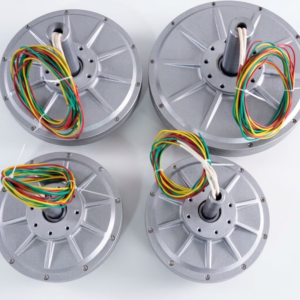
Compact axial flux alternator package with flat round housing and multi-phase output leads
Representative compact axial flux alternator package. Use the calculator to check whether the final design can stay inside a 100mm outside diameter and 35-45mm axial stack.

100mm generator calculator

100mm AFPM Generator Sizing Calculator
Estimate continuous power, torque, DC current, weight, and thickness for a 100mm outer-diameter axial flux BLDC generator based on speed, cooling, and voltage constraints.

1Design constraints

Typical useful range: 1,000-8,000 RPM. Hard screen limit: 12,000 RPM.

Liquid cooling raises continuous torque but adds thickness and weight.

Common compact battery and rectifier target. Current assumes a 92% rectifier and conversion path.

2Estimated performance

Continuous power
0.57kW
Continuous torque
1.80Nm
Estimated DC current
12.8A
48 V DC bus
Estimated weight
0.9kg
0.63 kW/kg
Axial thickness
35mm
Excludes shaft
Tip speed
15.7m/s
100mm outer diameter

At 3,000 RPM with air cooled, this screen estimates 0.57 kW continuous output and 1.80 Nm continuous torque. Use the current estimate to choose rectifier, wiring, and connector margin before requesting a detailed winding design.

Assumptions: Calculations use a 100mm outside diameter, first-pass continuous torque limits by cooling strategy, power = torque x RPM / 9549, and 92% rectifier/conversion efficiency for DC current. Output is a sizing screen, not final dyno, thermal, insulation, EMC, or rotor-retention validation.

Inquiry Email

[email protected]

Open RFQ Email

Please include application, peak/continuous torque, speed range, voltage/current limit, outer diameter, axial length, cooling method, quantity, and drawings or reference samples.

Instant Chat

+86 188 5797 1991

Chat on WhatsApp

Share torque-speed, package, cooling, and sample quantity in the first message.

Decision summary

What the estimate should make you decide

100mm diameter caps continuous torque first

The active radius is small, so continuous torque is the first feasibility limit. Air-cooled planning points should stay near 1.8 Nm; liquid cooling can screen up to about 3.5 Nm before detailed thermal work.

Evidence: Calculator assumptions reviewed July 23, 2026.

Voltage decides whether the result is electrically usable

The same mechanical power can be impractical at a low DC bus voltage because rectifier, cable, and connector current rise quickly. The tool therefore estimates current, not only shaft output.

Evidence: DC current uses output watts divided by bus voltage and 92% conversion efficiency.

High RPM needs rotor and loss validation

Above 8,000 RPM, tip speed, eddy-current loss, balance, and magnet retention risks become more important than the headline power number.

Evidence: Boundary state uses a 100mm outside-diameter tip-speed check.

Method and limits

Calculation basis shown before you use the result

The calculator is deterministic: the same inputs return the same output. Values are intentionally framed as planning screens because thermal, winding, rectifier, and rotor validation decide the final datasheet.

100mm generator calculation basis
VariableFormula or valueUseLimitation
Shaft powerkW = Nm x RPM / 9549Converts the continuous torque screen into usable generator output.Does not replace dyno or thermal validation.
Cooling torque limitAir: 1.8 Nm; liquid: 3.5 NmSeparates compact natural cooling from water-jacket planning points.Actual value depends on winding fill, housing, airflow, and duty cycle.
High-speed deratingTorque derates above 6,000 RPM to a 70% floorPrevents high-RPM power from looking unrealistically linear.Exact loss curve requires electromagnetic and thermal simulation.
Rectified DC currentA = output W / (bus V x 0.92)Screens rectifier, cable, connector, and controller-current pressure.Winding voltage constant and rectifier topology still need design work.
Tip speedm/s = RPM x pi x 0.1 / 60Flags rotor-retention and balance risk for the 100mm envelope.Rotor material, sleeve, adhesive, and magnet geometry are not modeled.

Use-case fit

Where a 100mm generator is likely to work

Application boundaries and next actions
ApplicationUseful inputLikely fitNext action
Small wind or VAWT generator100-1,000 RPM, 24-48 VPossible only with low-speed winding and startup reviewConfirm cut-in RPM, rectifier threshold, and cogging target.
Drone or mobile auxiliary power3,000-8,000 RPM, 48-96 VStrong when high RPM is available and mass is constrainedSend duty cycle, cooling airflow, and battery bus limits.
Compact engine or belt-driven alternator2,000-6,000 RPM, 48-96 VGood first-pass fit if shaft load and vibration are controlledValidate bearing loads, mounting flatness, and rectifier cooling.
Micro hydro direct drive100-800 RPM, 24-72 VUsually needs larger diameter unless gearing is acceptableCompare turbine speed curve against low-RPM output.

Related engineering paths

Continue from the sizing result

Use these internal references to move from the estimate to a product family, application boundary, validation gate, or RFQ.

100 RPM AFPM Generator Tool

Calculate sizing and limits for low-speed 100 RPM generators.

10.5kW AFPM motor calculator

Screen voltage, speed, current, and thermal limits for a motor request.

AFPM generator product family

Review direct-drive generator program scope and customization paths.

Renewable generator applications

Map wind and hydro speed ranges to generator sizing constraints.

Axial flux electric motor guide

Understand topology tradeoffs before choosing axial or radial flux.

Prototype validation gate

Use dyno, thermal, vibration, and inspection checks before production.

Send an engineering RFQ

Share RPM, voltage, duty cycle, package length, cooling, and quantity.

FAQ

Decision questions for a 100mm generator

Sizing

Can a 100mm axial flux generator make 1 kW continuously?

It can screen near or above 1 kW at high RPM with liquid cooling, but continuous rating depends on winding temperature, rectifier losses, and housing heat rejection.

Why does the tool ask for DC bus voltage?

Voltage determines current for the same output power. A low-voltage target can make wiring and rectifier heat impractical even when the mechanical output looks possible.

What RPM should I enter?

Enter the generator shaft speed after any pulley, gearbox, turbine, or engine coupling. Do not enter motor no-load speed or expected electrical frequency.

Boundaries

Why is there a warning above 8,000 RPM?

A 100mm rotor at high RPM needs magnet retention, rotor balance, bearing, and iron-loss validation. The calculator derates torque, then flags the point for engineering review.

Why is very low RPM treated as a boundary?

At very low speed, startup torque, cogging, winding resistance, and rectifier voltage drop decide whether useful power is available.

Does the estimate include efficiency?

It uses a 92% rectifier/conversion assumption for current and discloses the limitation. A final design still needs a measured efficiency map.

Next Steps

What should I send for an RFQ?

Send the copied calculator result plus application, peak and continuous duty cycle, available axial length, cooling method, voltage/current limits, and prototype quantity.

Can the same design work as a motor?

Some electromagnetic design choices overlap, but winding, inverter, thermal duty, sensor plan, and validation targets should be reviewed separately for motor operation.

Is this a finished datasheet?

No. It is a deterministic feasibility screen intended to decide whether a custom 100mm generator is worth detailed electromagnetic, thermal, and mechanical design.

Next step

Send the calculated point with duty-cycle context

The fastest path to a useful engineering reply is to copy the result, then include peak and continuous time windows, cooling method, package length, rectifier or battery voltage, and sample quantity. Unknown values can be marked N/A.

Inquiry Email

[email protected]

Open RFQ Email

Please include application, peak/continuous torque, speed range, voltage/current limit, outer diameter, axial length, cooling method, quantity, and drawings or reference samples.

Instant Chat

+86 188 5797 1991

Chat on WhatsApp

Share torque-speed, package, cooling, and sample quantity in the first message.