AFPM Motor LogoAFPM Motor
Start inquiry
AFPM Motor LogoAFPM Motor
WhatsApp
AFPM Motor LogoAFPM Motor

Axial flux permanent magnet motor OEM support for compact high-torque electric drive programs.

Inquiry Email

[email protected]

Open RFQ Email

Please include application, peak/continuous torque, speed range, voltage/current limit, outer diameter, axial length, cooling method, quantity, and drawings or reference samples.

Instant Chat

+86 188 5797 1991

Chat on WhatsApp

Share torque-speed, package, cooling, and sample quantity in the first message.

Products
  • Axial Flux PM Motors
  • Dual-Rotor AFPM Motors
  • Yokeless AFPM Motors
  • AFPM Stator & Rotor Assemblies
  • AFPM Generators
  • View All Products →
Solutions
  • Electric Motorcycle & Light EV
  • Robotics Compact Joint Drives
  • Drone & eVTOL Propulsion
  • Renewable Direct-Drive Generators
  • View All Solutions →
OEM Capabilities
  • AFPM Motor OEM Manufacturing
  • AFPM Design & Prototype Support
  • Rotor & Magnet Assembly
  • AFPM Quality Validation
  • View All Capabilities →
Resources
  • 10.5kW Motor Calculator
  • 3kW Coreless Generator Tool
  • 100mm Generator Calculator
  • 100 RPM Generator Tool
  • Blog
  • About
  • Contact / RFQ
  • Privacy Policy
  • Cookie Policy
  • Terms of Service
© 2026 AFPM Motor. All Rights Reserved.|AFPM Motor is the public-facing brand for axial flux permanent magnet motor OEM inquiries operated by Linkup Ai Co., Ltd.
Legal entity: Linkup Ai Co., Ltd.
Free deterministic sizing tool

3 kW AFPM Coreless Generator Calculator

Check whether your voltage, RPM, rotor diameter, and magnetic loading can support a 3 kW coreless axial flux generator before you buy magnets, wind coils, or request a custom build.

Published on July 29, 2026; last reviewed on July 29, 2026. The result is deterministic first-pass engineering guidance, not AI output or a substitute for electromagnetic, thermal, and rotor-stress validation.

Run feasibility checkSend generator RFQ
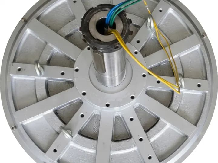
Coreless pancake axial flux generator reference for 3 kW feasibility screening
3 kW Coreless AFPM Feasibility Calculator

Screen whether your RPM, voltage, rotor diameter, and magnetic loading can support a 3 kW continuous coreless axial flux generator.

Range: 12-800 V DC. Example: battery or DC bus voltage.

Range: 50-6000 RPM at the generator shaft.

Range: 160-1200 mm for this first-pass screen.

Range: 0.25-0.95 T. Treat this as a magnet and air-gap estimate, not a measured result.

Results for 3 kW Output
Required Mech Torque
106.1Nm
Continuous shaft torque
Magnetic Torque Margin
4.54x
481.3 Nm estimated capacity
Mech Power Input
3.3kW
90% assumed efficiency
Electrical Current
62.5A
At 48 V DC
Rotor Rim Speed
8.2m/s
Stress screening input
Cogging Torque
0Nm
Coreless stator benefit
Feasible first-pass design point

The selected inputs leave a workable first-pass margin for a 3 kW coreless AFPM generator.

At 300 RPM, the prime mover must supply 106.1 Nm continuously. The selected 520 mm rotor and 0.62 T air-gap estimate provide about 481.3 Nm of heuristic torque capacity (4.54x margin).

Next Engineering Action

Confirm blade swept area, cut-in speed, and local wind distribution before assuming the rotor can supply this torque continuously.

Direct-drive wind turbines operate at low RPM, so the same 3 kW output demands high continuous shaft torque and a larger magnetic diameter.

Assumptions: 3 kW electrical output, 90% nominal efficiency, dual-air-gap coreless AFPM topology, continuous torque, and a heuristic magnetic shear-stress model. Final winding, losses, temperature rise, rotor stress, and magnet retention require engineering validation.

Inquiry Email

[email protected]

Open RFQ Email

Please include application, peak/continuous torque, speed range, voltage/current limit, outer diameter, axial length, cooling method, quantity, and drawings or reference samples.

Instant Chat

+86 188 5797 1991

Chat on WhatsApp

Share torque-speed, package, cooling, and sample quantity in the first message.

Key conclusions

RPM drives required torque

A 3 kW electrical target needs about 3.33 kW mechanical input at the default 90% efficiency assumption. At 300 RPM, that is about 106 Nm continuous shaft torque.

Evidence: The calculator uses Torque = mechanical watts / angular speed and updates the result from the RPM input.

Diameter and flux set magnetic margin

Coreless AFPM designs have no iron teeth, so rotor diameter, magnet strength, air-gap control, and dual-rotor geometry decide whether the target torque is realistic.

Evidence: The tool estimates torque capacity from rotor OD and air-gap flux density, then reports a torque-margin ratio.

Zero cogging is not zero risk

A coreless stator avoids cogging torque, but high current, rotor stress, copper heating, magnet retention, and low-speed torque still need validation.

Evidence: Boundary states flag high torque, high current, low magnetic margin, low flux density, and high rim speed.

Calculation methods

VariableFormulaUseLimitation
Mechanical inputkW_mech = 3.0 / 0.90Converts the 3 kW electrical target into required shaft power.90% is a screening assumption; final efficiency depends on winding, rectifier, cooling, and speed.
Required torqueNm = W_mech / (RPM x 2 x pi / 60)Shows whether the prime mover can physically turn the generator at 3 kW.Does not include overload, gust, startup, or bearing friction margin.
Electrical currentA = 3000 W / VdcScreens conductor size, rectifier losses, connector rating, and thermal load.Actual phase current depends on winding, rectification, waveform, and controller strategy.
Magnetic torque marginCapacity / required torqueCompares selected rotor OD and flux estimate against a dual-gap coreless AFPM torque heuristic.Not a substitute for electromagnetic FEA, prototype dyno data, or thermal validation.
Rotor rim speedm/s = pi x diameter(m) x RPM / 60Flags when mechanical stress, balance, and magnet retention deserve early review.Material grade, adhesive, sleeve, and rotor disk design set the real limit.

Worked example: 3 kW wind profile

MetricResultDecision Use
Default wind profile48 V, 300 RPM, 520 mm OD, 0.62 TUseful first screen for a low-speed direct-drive generator concept before blade matching.
Required shaft torqueAbout 106 NmIf the turbine cannot sustain this torque near the target RPM, 3 kW output is not realistic.
Electrical currentAbout 62.5 A at 48 VLow-voltage systems need heavier conductors and careful rectifier thermal design.
Magnetic marginAbout 4.5x in the heuristic modelThis suggests magnetic loading is not the first bottleneck, but thermal and structural checks still matter.
Rotor rim speedAbout 8.2 m/sLow rim speed is mechanically manageable; higher RPM profiles should be checked for retention risk.

Application fits

ApplicationUseful InputLikely FitNext Action
Small wind turbine48-120 V, 150-500 RPMBest when zero cogging and low cut-in speed matter more than minimum magnet cost.Compare calculated torque with the blade torque curve at real wind speeds.
Micro-hydro48-240 V, 500-1800 RPMOften practical because water flow can provide steadier torque and cooling.Match generator speed to turbine type, head, flow rate, and rectifier plan.
Engine generator240-800 V, 1800-3600 RPMCompact package is possible, but high-speed balancing and overspeed voltage need review.Define idle, governed speed, overspeed, target DC bus, and cooling airflow.
Dyno / test rig48-400 V, 500-3000 RPMUseful for controllable bench loads where smooth torque and simple rectified output are needed.Confirm coupling torque, load bank rating, duty cycle, and data acquisition needs.

Design boundaries to verify

Coreless does not mean iron-free losses disappear

The stator removes cogging and tooth loss, but copper loss, rectifier loss, eddy current in conductors, and rotor magnet heating can still dominate at 3 kW.

Air-gap discipline matters

A small change in air gap can reduce effective flux density and erase margin. Rotor flatness, bearing stiffness, and assembly fixtures should be defined before tooling.

Thermal path is usually the real constraint

A resin-embedded coreless coil has less iron mass to absorb heat. Continuous output needs winding temperature limits, insulation class, cooling method, and duty cycle.

Frequently asked questions

Inputs

Why does the 3 kW calculator ask for rotor diameter?

At low RPM, torque is the limiting requirement. Rotor outside diameter is a practical proxy for air-gap area, so it helps screen whether the selected magnetic package has enough torque capacity.

What air-gap flux density should I enter?

Use a conservative estimate if you do not have measured data. For early screening, 0.55-0.75 T is a practical placeholder range for strong permanent-magnet axial-flux concepts, but the real value depends on magnet grade, air gap, and rotor geometry.

Output

Is a torque margin above 1.0 enough?

Not by itself. A value above 1.0 only means the simplified magnetic heuristic clears the continuous torque target. Real designs need thermal, voltage, mechanical, tolerance, and duty-cycle margin.

Why does low voltage create a warning?

For the same 3 kW output, lower voltage means higher current. High current increases copper loss, connector size, rectifier heat, and winding packaging difficulty.

Coreless Design

Is cogging torque really zero?

A coreless stator removes iron teeth, so cogging torque is effectively eliminated. Bearing friction, seal drag, windage, and electrical loading still create startup and running torque.

Why use a dual-rotor layout?

A dual-rotor coreless AFPM closes the magnetic path across the stator coils and improves usable flux. Single-sided layouts usually leave too much leakage for compact 3 kW designs.

Manufacturing

Can this replace detailed electromagnetic design?

No. The calculator is a first-pass feasibility screen. Before sourcing magnets, coils, tooling, or housings, validate winding turns, voltage, losses, thermal rise, rotor stress, and dyno output.

What should I send for an RFQ?

Send target RPM range, voltage or rectifier plan, continuous and peak output, rotor OD limit, axial length, cooling method, enclosure, duty cycle, environment, and prototype quantity.

Sources and calculation boundaries

SourceUse on This Page
Calculation methods on this pageTorque, current, magnetic-margin, and rim-speed formulas are disclosed for reproducibility.
Review statusThis page was published on July 29, 2026 and last reviewed on July 29, 2026; formulas are deterministic and do not use AI output.
OEM validation boundaryFinal design requires torque-speed curve, winding, thermal, rotor-stress, and prototype dyno validation.

Related tools and next steps

100 RPM axial flux generator tool

Use this when speed is fixed at 100 RPM and you need diameter, torque, pole-count, and weight screening.

100mm axial flux BLDC generator calculator

Use this when the package diameter is fixed and you need to estimate output inside a small axial-flux envelope.

AFPM generator manufacturing support

Review custom generator topology, voltage, rotor, stator, housing, and validation requirements.

Rotor and magnet assembly

Use this when magnet retention, balancing, bonding, coating, or rotor disk tolerances are the main project risk.

Need a manufacturable 3 kW coreless generator?

Send the calculated torque, target voltage, rotor OD limit, axial length, air-gap assumptions, cooling method, environment, duty cycle, and prototype quantity so engineering can screen whether a coreless AFPM generator is the right architecture.

Inquiry Email

[email protected]

Open RFQ Email

Please include application, peak/continuous torque, speed range, voltage/current limit, outer diameter, axial length, cooling method, quantity, and drawings or reference samples.

Instant Chat

+86 188 5797 1991

Chat on WhatsApp

Share torque-speed, package, cooling, and sample quantity in the first message.