AFPM Motor LogoAFPM Motor
Start inquiry
AFPM Motor LogoAFPM Motor
WhatsApp
AFPM Motor LogoAFPM Motor

Axial flux permanent magnet motor OEM support for compact high-torque electric drive programs.

Inquiry Email

[email protected]

Open RFQ Email

Please include application, peak/continuous torque, speed range, voltage/current limit, outer diameter, axial length, cooling method, quantity, and drawings or reference samples.

Instant Chat

+86 188 5797 1991

Chat on WhatsApp

Share torque-speed, package, cooling, and sample quantity in the first message.

Products
  • Axial Flux PM Motors
  • Dual-Rotor AFPM Motors
  • Yokeless AFPM Motors
  • AFPM Stator & Rotor Assemblies
  • AFPM Generators
  • View All Products →
Solutions
  • Electric Motorcycle & Light EV
  • Robotics Compact Joint Drives
  • Drone & eVTOL Propulsion
  • Renewable Direct-Drive Generators
  • View All Solutions →
OEM Capabilities
  • AFPM Motor OEM Manufacturing
  • AFPM Design & Prototype Support
  • Rotor & Magnet Assembly
  • AFPM Quality Validation
  • View All Capabilities →
Resources
  • 10.5kW Motor Calculator
  • 3kW Coreless Generator Tool
  • 100mm Generator Calculator
  • 100 RPM Generator Tool
  • Blog
  • About
  • Contact / RFQ
  • Privacy Policy
  • Cookie Policy
  • Terms of Service
© 2026 AFPM Motor. All Rights Reserved.|AFPM Motor is the public-facing brand for axial flux permanent magnet motor OEM inquiries operated by Linkup Ai Co., Ltd.
Legal entity: Linkup Ai Co., Ltd.

Published July 29, 2026; reviewed July 29, 2026

3 Phase Axial Flux Motor Calculator

Estimate line voltage, phase voltage, RMS phase current, and peak phase current before you ask a supplier to wind a custom 3 phase axial flux motor.

Default screen

50kW output, 400V DC bus, 0.95 efficiency, 0.90 power factor, Wye winding.

Use the result for

Inverter current class, cable sizing conversation, and RFQ evidence requests.

Request Engineering ReviewReview EvidenceRFQ Checklist
3-Phase Axial Flux Motor Calculator
Estimate phase currents and voltages to size your inverter and cables for a 3-phase AFPM.

Motor & Inverter Setup

Common EV voltages: 48, 96, 400, 800

Calculation Results

Phase Current (RMS)

119.4 A

Peak Phase Current

168.8 A

Phase Voltage (RMS)

163.3 V

Line Voltage (RMS)

282.8 V

First-pass estimate ready

Phase parameters calculated from the stated voltage, power, efficiency, power factor, and winding connection.

Review the phase current to size your inverter and cables.

Note: Calculation assumes a standard 3-phase inverter using Space Vector PWM (SVPWM) where maximum line-to-line RMS voltage is approximately 0.707 × DC Bus Voltage.

Inquiry Email

[email protected]

Open RFQ Email

Please include application, peak/continuous torque, speed range, voltage/current limit, outer diameter, axial length, cooling method, quantity, and drawings or reference samples.

Instant Chat

+86 188 5797 1991

Chat on WhatsApp

Share torque-speed, package, cooling, and sample quantity in the first message.

ISO 9001Quality Management
CE & RoHSEU Compliance
IP55 – IP67Protection Available
UL / CSAInsulation System
OEM ReadyPrototype to Volume
-40°C to +160°CThermal Validated
Decision Summary

What the calculator tells you before supplier selection

The report layer does not compete with the tool. It explains how to interpret the current estimate, which evidence to ask for, and where a nominal kW match can still fail.

1

Start with inverter current, not only rated kW

A 3 phase axial flux motor can look compact at the motor housing while still forcing very high RMS and peak current through the inverter, busbars, and phase cables.

Evidence:The calculator uses P = sqrt(3) x Vline,rms x Iline,rms x power factor and flags high-current cases before they become packaging or thermal problems.
2

Assume 3-phase BLDC/PMSM until the datasheet proves otherwise

For OEM procurement, the practical default is a 3-phase permanent-magnet axial flux machine driven by a BLDC/PMSM inverter. Exact winding, sensor, and control details still need supplier confirmation.

Evidence:Public axial-flux product literature is dominated by traction and industrial inverter-driven permanent-magnet machines, but public pages do not prove a universal market share.

3

Wye and Delta change the electrical match

Wye keeps phase current equal to line current and lowers phase voltage by sqrt(3). Delta keeps phase voltage equal to line voltage and lowers phase current by sqrt(3), but can raise harmonic-current risk.

Evidence:The calculator exposes Wye and Delta because the same DC bus and kW target can imply different phase-current and phase-voltage requirements.

4

Continuous duty requires thermal evidence

Peak current is useful for acceleration, launch, or short bursts. Continuous operation needs coolant temperature, winding temperature limit, flow rate, and a torque-speed or efficiency map.

Evidence:The RFQ checklist separates electrical interface data from thermal validation so a peak-power claim is not mistaken for an S1 continuous rating.

System Boundary

A 3-phase AFPM is a motor, inverter, and thermal package

The same motor housing can become a clean production drive or a current-limited prototype depending on DC bus voltage, inverter RMS current, winding connection, and cooling path.

DC source, inverter, and 3-phase axial flux motor boundaryBattery / DC Link48V to 800V+3-Phase InverterCurrent and voltage limitSVPWM / field weakeningAxial FluxMotorDC currentU / V / WCalculator screens this boundary; final design still needs measured motor and inverter maps.
AssumptionValueUse / Limit
Default calculation point50kW mechanical output, 0.95 efficiency, 0.90 power factorUse the calculator for your actual voltage, kW target, and winding assumption.
Voltage modelVline,rms ~= Vdc x 0.707First-pass SVPWM screening value; controller limits and modulation strategy can change available voltage.
Power equationIline,rms = Pelectrical / (sqrt(3) x Vline,rms x PF)Mechanical output is divided by efficiency before current is estimated.
Procurement limitNot a datasheet replacementFinal sizing needs Ke, Kt, phase resistance, inductance, torque-speed map, and thermal test data.
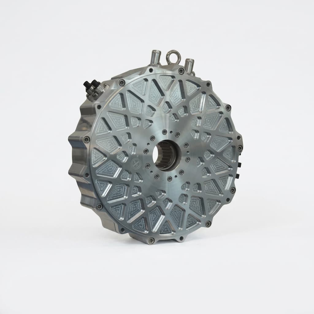
Automotive axial flux motor package used as a 3-phase motor integration reference

Practical interpretation

If the result shows hundreds of amps at a low-voltage bus, do not treat the motor diameter as the only packaging constraint. The inverter, phase conductors, connector system, and coolant loop now drive the design.

Evidence And Method

Current screening examples and winding interpretation

These examples use the same 50kW, 0.95 efficiency, 0.90 power factor, Wye calculation point as the default tool state. They are not final motor recommendations.

Wye and Delta winding relationship diagramWye / StarL1L2L3Higher voltage constant; common torque-first defaultDeltaL1L2L3Higher-speed option; confirm harmonic-current control
DesignElectrical RuleBest FitRisk
3-phase Wye / StarIphase = Iline; Vphase = Vline / sqrt(3)Low-speed torque, compact EV traction drives, AGV and AMR wheel modules.Can hit high phase current quickly on 48V and 96V platforms.
3-phase DeltaIphase = Iline / sqrt(3); Vphase = VlineHigher-speed designs where voltage utilization matters more than launch torque.Can create circulating harmonic currents if the winding and controller are not designed together.
Dual 3-phaseTwo isolated 3-phase sets, usually driven by paired invertersAviation, marine propulsion, and safety-critical equipment needing redundancy.Raises inverter count, harness complexity, calibration effort, and validation cost.
DC BusUsable Line RMSPhase CurrentPeak CurrentDecision Signal
48V DC~33.9V RMS~995A RMS~1,407AUsually impractical for 50kW unless the package uses very large conductors and short burst duty.
96V DC~67.9V RMS~497A RMS~703APossible for short bursts, but inverter and connector thermal limits dominate the design.
400V DC~282.8V RMS~119A RMS~169AA more realistic traction-voltage screening point for light EV and industrial packages.
800V DC~565.7V RMS~60A RMS~84ACurrent is cleaner, but insulation, safety, and inverter cost move up.

Sources, Dates, And Limits

AFPM Motor 3-phase calculator model

Updated July 29, 2026

Uses Vline,rms ~= Vdc x 0.707 under a first-pass SVPWM assumption, then estimates line RMS current from three-phase real power.

Confidence:High for arithmetic screening; medium for hardware until verified with motor constants, inverter limits, and dyno data.

Open calculator

YASA P400-R public product page

Reviewed July 29, 2026

A production-oriented axial-flux benchmark should be read as a specific motor/inverter package, not as a generic rule for every 3 phase axial flux motor.

Confidence:High for the existence of the published product page; medium when extrapolated to custom procurement.

YASA product page

Imperix SVPWM technical note

Reviewed July 29, 2026

Space-vector PWM changes voltage utilization compared with sinusoidal PWM, so DC bus voltage and modulation method must be stated in the inverter match.

Confidence:Medium-high for modulation context; final value depends on controller implementation and limits.

SVPWM note

Astrodyne TDI, 3-phase Delta vs Wye overview

Reviewed July 29, 2026

Wye and Delta connections use different line-to-phase voltage/current relationships, which changes phase-current interpretation.

Confidence:Medium for fundamentals summary; supplier winding drawings remain the procurement source of truth.

Y/Delta reference

AFPM Motor inquiry workflow

Updated July 29, 2026

RFQ review should request DC bus range, inverter RMS/peak current, winding connection, torque-speed map, and cooling data in one package.

Confidence:High for internal review process; final design remains application-specific.

RFQ checklist
Limits And Risk

Where a plausible calculator result can still fail

Treat these risks as review gates. A supplier quote that does not resolve them is not ready for prototype approval.

3-phase axial flux motor risk matrixLikelihood during integrationImpact on launchWye/DeltawordingCoolingproofInvertercurrentWrongsupply

Single-phase supply misunderstanding

High

Trigger:Specifying a “3 phase axial flux motor” but expecting it to run directly from wall AC.

Mitigation:Use a VFD or BLDC/PMSM inverter that synthesizes the motor-side three-phase waveform.

Inverter derating before motor limit

High

Trigger:Peak or RMS current exceeds module, capacitor, connector, or cooling limits.

Mitigation:Raise DC bus voltage, reduce peak torque, change winding turns, or select a higher-current inverter.

Thermal saturation hidden by peak kW

High

Trigger:Short burst power is treated as continuous S1 output.

Mitigation:Ask for coolant conditions, winding temperature rise, duty cycle, and dyno evidence.

Wye/Delta assumption mismatch

Medium

Trigger:Supplier and buyer quote “phase current” while using different winding definitions.

Mitigation:Require winding diagram, line current, phase current, phase voltage, and controller RMS/peak definitions.

PlatformTypical DC BusDecision Focus
AGV / AMR drive module48-96VCheck current first. Low-voltage systems often hit connector and busbar limits before motor packaging limits.
Light EV / motorcycle96-400VMatch peak launch torque to inverter current, then verify cooling for hill climbs and repeated acceleration.
Drone / eVTOL auxiliary drive400-800VPrioritize mass, redundancy, insulation clearance, bearing load, and fault handling over raw kW density.
Industrial pump or fan400-800VTreat continuous duty, thermal stability, ingress protection, and service life as the primary gate.
RFQ Checklist

Minimum data to request after the first calculation

Send the calculator result with these evidence requests so the supplier answers electrical, thermal, and mechanical fit in the same review cycle.

Data AreaAsk The Supplier ForDecision It Supports
Inverter interfaceDC bus range, line RMS current, peak phase current, switching frequency, sensor type, and field-weakening limit.Confirms whether the controller can actually deliver the torque-speed target.
Motor constantsKt, Ke, phase resistance, phase inductance, pole count, winding connection, and temperature basis.Prevents generic kW comparisons from hiding voltage and current incompatibility.
Thermal evidenceCoolant type, flow rate, inlet temperature, winding limit, thermal sensor location, and derating curve.Separates peak launch power from continuous production duty.
Mechanical packageOuter diameter, axial length, mass, shaft/bearing loads, mounting face, IP rating, and resolver or encoder package.Validates the axial-flux packaging advantage against real integration constraints.
Validation dataTorque-speed map, efficiency map, NVH notes, insulation class, hipot result, and thermal-cycle report.Gives procurement enough evidence to move from calculator screening to prototype approval.
FAQ

Common questions about 3 phase axial flux motors

Electrical Basics

Is a 3 phase axial flux motor AC or DC?

The motor-side waveform is three-phase AC generated by an inverter. The system may be fed by a DC battery or DC link, but the inverter still controls phase current and frequency.

Can it run directly from single-phase power?

No. A single-phase supply must feed a VFD or BLDC/PMSM inverter that creates the motor-side three-phase output.

Why does DC bus voltage affect phase current?

For the same mechanical output, a higher usable line RMS voltage lowers the line RMS current required by the three-phase power equation.

Is phase current the same as battery current?

No. Battery or DC-link current is an input-side value. Motor phase RMS current depends on modulation, winding connection, motor constants, and operating point.

Winding And Inverter Match

Should I choose Wye or Delta?

Choose Wye when launch torque and lower-speed control dominate. Choose Delta only when the motor and controller are designed for higher-speed operation and harmonic-current risk is addressed.

What happens if peak phase current is above the inverter rating?

The inverter will current-limit, thermally derate, fault, or fail depending on protection design. The motor will not reach its advertised peak torque.

Does an 800V system always solve the problem?

It lowers current for the same power, but it raises insulation, safety, connector, and inverter cost requirements.

Why include power factor in the calculator?

The real power delivered by a three-phase machine depends on voltage, current, and power factor. Using a realistic PF avoids underestimating current.

Procurement And Validation

What is the minimum RFQ data package?

Request DC bus range, inverter RMS and peak current, winding connection, Kt, Ke, phase resistance, cooling conditions, torque-speed map, and efficiency map.

Can I compare suppliers by kW per kg only?

No. Compare mass only after rating basis, cooling hardware, duty cycle, controller mass, and test temperature are stated.

How should I use the calculator result?

Use it as a screening result to decide whether the voltage/current target is plausible, then ask the supplier for measured data at your exact operating point.

What makes a result unsafe for production?

Missing thermal data, undefined current basis, no winding diagram, no inverter derating curve, or no torque-speed map should stop production approval.

Next Step

Send the calculation point for engineering review

Include your DC bus voltage, target kW, duty cycle, winding assumption, allowable phase current, cooling method, and package envelope. The engineering team can then respond with a winding and inverter review instead of a generic brochure.

Inquiry Email

[email protected]

Open RFQ Email

Please include application, peak/continuous torque, speed range, voltage/current limit, outer diameter, axial length, cooling method, quantity, and drawings or reference samples.

Instant Chat

+86 188 5797 1991

Chat on WhatsApp

Share torque-speed, package, cooling, and sample quantity in the first message.

Related Engineering Pages

Axial Flux PM Motor

Review the permanent-magnet topology and RFQ scope.

Motorcycle & Light EV Drives

Map motor voltage, torque, and cooling choices to light EV use.

Drone & eVTOL Propulsion

Compare mass, redundancy, and high-voltage integration tradeoffs.

AFPM Quality Validation

See the validation evidence to request before prototype approval.