
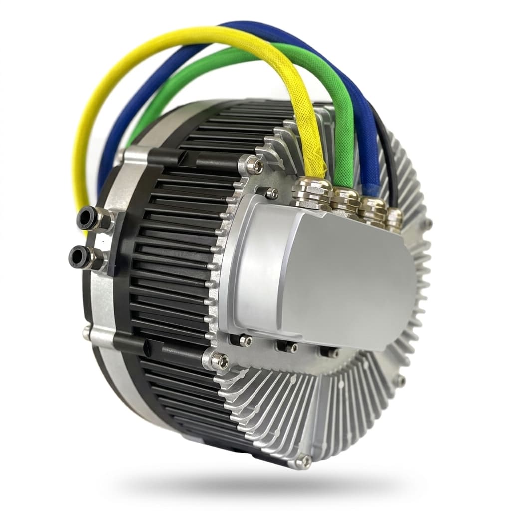
High-Speed Axial Flux Rotor Magnet Retention: Carbon Fiber Sleeves, Hoop Stress & Tip Speed Limits
Compare high-speed axial flux rotor magnet retention, carbon fiber sleeves, hoop stress and thermal fit. Use the RFQ checklist to define qualification evidence.
High-speed axial flux rotor magnet retention requires a defined load path from each magnet into the rotating structure. A carbon fiber retaining hoop can resist outward radial motion with low added mass, but it does not by itself restrain axial separation, disc bending, or magnet tilting. Retention selection must consider the complete rotor geometry, temperature range, operating speed, and qualification evidence.
There is no universal safe tip speed for an adhesive, pocket, metallic ring, or carbon fiber sleeve. Calculate the loads first, compare viable retention architectures, then agree on analysis and test acceptance criteria. This guide gives engineering and procurement teams a worked example, a comparison matrix, and an RFQ checklist for that decision.
Scope and review date — November 3, 2026: This Global-English engineering guide covers surface-mounted permanent magnet (SPM) and Halbach-array axial flux rotors. Calculations are illustrative screening estimates, not measured AFPM Motor performance, released sleeve dimensions, or aerospace certification evidence. A qualified rotor design needs geometry-specific electromagnetic, structural, thermal, and rotor-dynamic validation.
Preparing an RFQ? Start with the drawing and speed envelope for your rotor magnet assembly, including the axial retention features as well as the outer hoop.
1. Centrifugal Dynamics and Tip Speed Limits in AFPM Rotors
Axial flux rotors carry magnets on a disc face. Centrifugal loading acts radially in that plane; magnetic attraction and disc deflection introduce separate axial demands. An outer-diameter hoop can carry radial loads only where pockets, fillers, or magnet edges transfer those loads into it. Adhesive also carries torque and may contribute to radial and axial restraint; its adequacy depends on the actual joint and hot, aged properties.
For a magnet segment, use the radius to its center of mass, not the outer tip radius:
ω = 2πN / 60(rad/s), whereNis speed in RPM.v_tip = ω × r_o(m/s), wherer_ois the outer radius in meters.F_c = m × ω² × r_g(N), wheremis magnet mass in kg andr_gis its center-of-mass radius in meters.
Reproducible example: Assume a 300 mm rotor diameter, 14,000 RPM, a 0.040 kg magnet, and r_g = 0.120 m. Angular velocity is about 1,466 rad/s and tip speed is about 220 m/s. The outer-rim acceleration is about 322,400 m/s² (32,900 g), while the magnet center-of-mass acceleration is about 257,900 m/s² (26,300 g). The magnet's outward force is therefore about 10.3 kN.
That force is a load input, not a sleeve rating or proof that a particular adhesive fails. The simplified segment calculation neglects its distributed mass and local stress concentrations. Check bond area, peel loading, surface preparation, thermal aging, carrier strength, and the mechanical load path before selecting retention. At fixed geometry, increasing speed by 20% increases centrifugal load by 44% because force scales with speed squared.
2. Retention Topologies: CFRP vs. Titanium vs. Recessed Disc Pockets
A. Carbon Fiber Reinforced Polymer (CFRP) Hoops
Circumferential fibers provide useful tensile stiffness and strength for radial containment. Low composite density reduces the hoop's own centrifugal stress. However, fiber grade alone does not specify a finished sleeve: resin, fiber volume, winding angle, cure, voids, joints, and environmental conditioning all affect the allowable load.
Carbon fiber is electrically conductive. Toray's T700S data sheet lists fiber resistivity, so zero eddy-current loss must not be assumed. Finished-sleeve electrical behavior depends on the laminate. Calnetix's rotor-retention guidance also identifies the thermal-barrier and reduced harmonic-shielding trade-offs of carbon fiber sleeves. Its PM-machine guidance supports these principles; it does not qualify a particular axial flux rotor.
B. High-Strength Metallic Rings (Titanium / Inconel)
A metallic ring offers a different combination of stiffness, thermal expansion, heat transfer, and manufacturing tolerances. Its density raises self-stress at a given speed. Conductive rings can shield magnets from harmonic fields while dissipating heat in the ring itself, so compare total rotor loss and cooling, not sleeve loss alone. Neither titanium nor Inconel has a universal loss in watts or an application-independent temperature limit for the complete rotor.
C. Recessed Mechanical Disc Pockets
Pockets, lips, or covers can provide positive mechanical restraint, sometimes combined with adhesive and an outer hoop. Check the carrier's local stress concentrations and the effect on useful magnetic area. Steel back iron, a non-magnetic carrier, and a yokeless rotor are different magnetic architectures; their retention penalties cannot be reduced to one generic percentage of flux loss.
3. Engineering Comparison: Rotor Magnet Retention Topologies
Use this matrix to structure a supplier comparison. Entries describe design dependencies rather than qualified speed, cost, or temperature ratings.
| Decision criterion | Adhesive-led joint | Recessed pocket / lip | Metallic ring | CFRP hoop |
|---|---|---|---|---|
| Radial load path | Bond shear and local peel | Magnet-to-pocket contact and carrier stress | Contact load into hoop tension | Contact load into circumferential fibers |
| Axial magnet restraint | Depends on bond and support geometry | Requires a suitable lip, cover, or bond | Outer ring alone may not restrain axial lift | Outer hoop alone may not restrain axial lift |
| Tip speed limit | Joint-specific analysis and test | Carrier and notch-stress analysis | Ring, magnet, and carrier analysis | Laminate, interface, and carrier analysis |
| Strength evidence | Conditioned joint tests with actual surfaces | Material condition plus local stress model | Alloy condition and temperature-dependent properties | Finished-laminate data; fiber strength is insufficient |
| Self-stress concern | Bond also carries magnet loads | Carrier inertia and local geometry | Density increases rotating-ring self-stress | Lower density can reduce rotating-ring self-stress |
| Electromagnetic loss | Check magnets and carrier | Geometry and carrier conductivity matter | Sleeve heating and magnetic shielding interact | Conductivity is anisotropic; magnet loss still matters |
| Thermal boundary | Adhesive, coating, and magnet limits | Carrier, bond, and magnet limits | Whole-assembly limits, not alloy capability alone | Resin, interface, and magnet limits; assess heat removal |
| Assembly control | Surface preparation, bondline, and cure | Clearances, corner radii, and contact | Fit tolerance, surface finish, and assembly temperatures | Winding tension/cure or sleeve fit; edge protection |
| Qualification evidence | Aged joints plus rotor tests | Local stress validation and rotor tests | Dimensional records, balance, and spin tests | Process/inspection records, laminate evidence, and spin tests |
4. Mechanics of Hoop Stress and Interference Sizing
4.1 Thin-Ring Self-Stress: A Screening Calculation
For a thin, uniform rotating ring, the hoop self-stress is approximated by:
σ_self = ρ × ω² × r_m² = ρ × v_m²
Use density ρ in kg/m³ and the speed v_m at the ring mean radius, not automatically at the rotor tip. At an assumed mean-ring speed of 250 m/s:
- An assumed Inconel density of 8,190 kg/m³ gives about 512 MPa of self-stress.
- An assumed CFRP density of 1,550 kg/m³ gives about 97 MPa of self-stress.
These are illustrative density assumptions, not batch-certified properties. Thickness does not enter this idealized self-stress equation, but it does affect the hoop's ability to carry magnet contact loads. Neither result predicts burst speed or a remaining strength margin.
Do not substitute fiber strength for sleeve strength. For example, Toray's T700S sheet gives nominal fiber tensile strength of 4,900 MPa, but nominal composite tensile strength of 2,550 MPa for the stated resin system at room temperature and 60% fiber volume. Neither is a hot, aged design allowable for a finished retaining ring.
4.2 Contact Load and Total Hoop Stress
For a thin ring under approximately uniform radial pressure, a preliminary membrane estimate is:
σ_θ ≈ ρ × ω² × r_m² + p × r_i / t_s
Here p is operating contact pressure in Pa, r_i is sleeve inner radius in meters, and t_s is radial wall thickness in meters. Operating contact pressure includes the assembly preload and its changes with speed and temperature; do not add the same preload twice.
For illustration only, p = 2 MPa, r_i = 0.150 m, and t_s = 0.001 m add 300 MPa of hoop stress. Combined with the assumed CFRP self-stress above, the estimate is about 397 MPa. This does not approve a 1 mm sleeve: discrete magnet contact, anisotropy, residual cure stress, carrier deformation, edge effects, and strength knockdowns require a detailed model. The assumed 2 MPa is not a minimum-pressure specification.
4.3 Thermal Interference Fit: Define the Interface First
Define radial interference as δ₀ = r_carrier,OD − r_sleeve,ID at the assembly reference temperature; positive means interference. For a segmented rotor, the carrier radius means the supported outer contact envelope, including the magnet/filler geometry. Diametral interference is twice radial interference, so an RFQ must identify which convention it uses.
A useful free-displacement bookkeeping relation is:
δ_free(N, T) = δ₀ + u_carrier,free(N, T) − u_sleeve,free(N, T)
The u terms are unconstrained radial displacements relative to assembly conditions. They are not contact pressure. A contact model must convert the mismatch into interface pressure and stress using both components' compliance, tolerances, and contact conditions.
Heating a metal carrier inside a low-expansion hoop can increase interference; cold conditions can reduce it. Thermal gradients, magnet orientation, resin relaxation, and centrifugal growth can change the result. Evaluate cold standstill, cold overspeed, hot standstill, and hot overspeed, including tolerances and aging. Require adequate radial restraint without crushing magnets or overloading the hoop. Separately check axial adhesive/pocket restraint and disc-to-stator clearance. There is no generally valid interference range or universal minimum contact pressure for a 200–300 mm AFPM rotor.
5. Manufacturing & Assembly: Direct Filament Winding vs. Pre-Cured Sleeves
Method 1: Direct Wet / Tow-Preg Filament Winding
Winding directly onto a supported rotor can introduce hoop preload and conform to its contact envelope. Specify winding tension, layer architecture, edge protection, cure records, and inspection acceptance criteria. The cure must be compatible with magnets, coatings, and adhesive. Resin flow and cure shrinkage change residual stress, so tow tension alone does not establish the final preload.
Method 2: Assembly of Pre-Cured Composite Sleeves
A pre-cured sleeve permits separate dimensional and material inspection. Assembly may use a qualified press-fit or controlled temperature differential, but clearance must be calculated from actual thermal expansion and tolerances. Low hoop-direction expansion means simply warming a CFRP sleeve may create little clearance. Unqualified liquid-nitrogen immersion can damage magnets, coatings, adhesive, or composite interfaces and is not a general assembly procedure.
For both routes, request process records and an agreed void/delamination acceptance criterion rather than a claim of zero void content. Define how sleeve dimensional measurements, nondestructive inspection, and assembly traceability connect to the validated rotor design.
6. Sourcing & Procurement Checklist: High-Speed AFPM Rotors
Use these eight gates before accepting a supplier's speed or retention claim:
- 1. Speed envelope and spin qualification: Record rated speed, maximum commanded speed, fault/overspeed cases, test temperature, duration, and acceptance criteria. At 120% of 15,000 RPM, the test point would be 18,000 RPM; this is an arithmetic example, not a universal standards requirement. Define proof-spin and destructive burst tests separately.
- 2. Composite architecture and thermal properties: Identify fiber, resin, winding orientation, fiber volume, cure, and conditioned laminate properties. Obtain temperature-dependent allowables and the method/conditioning used to measure glass transition temperature (
T_g). Agree on a service-temperature margin for the actual resin system. - 3. Interface and tolerance model: Request radial/diametral fit definitions and a speed-temperature-tolerance matrix. Identify each contact interface and demonstrate adequate radial restraint, acceptable magnet compression, and independent axial retention.
- 4. Magnet edges and load transfer: Show chamfers/radii, fillers, pocket contact, adhesive bondline, and torque path on the drawing. Set geometry-specific limits that avoid fiber damage, local magnet fracture, and axial clearance loss.
- 5. Balance and rotor dynamics: Specify residual unbalance, correction planes, runout, and the agreed balancing procedure. ISO 21940-11:2016 addresses rotors with rigid behavior; it neither mandates one balance grade for all high-speed AFPM rotors nor certifies overspeed strength. Assess flexible behavior and critical speeds separately.
- 6. Rotor loss and thermal verification: Require a loss model and a test method covering the magnets, carrier, and retaining ring at representative inverter excitation. Define rotor-temperature measurement or validated estimation; external surface images alone may miss internal hot spots.
- 7. Composite inspection and traceability: Agree on qualified inspection methods, defect limits, calibration/reference samples, sampling or full inspection, and lot records. A visual check is not equivalent to ultrasonic inspection of internal delamination.
- 8. Adhesive qualification: Specify the actual adhesive, surface preparation, coating compatibility, cure, and hot/aged shear and peel evidence. A thermal class label or coupon result alone does not qualify a complete rotating joint.
Use the AFPM quality validation service to discuss which analysis, inspection, and test records your program needs. Agree on evidence availability and acceptance criteria before releasing a purchase order.
7. Frequently Asked Questions (FAQ)
Q1: Can glass fiber replace carbon fiber in a rotor retaining sleeve?
Glass fiber offers electrical insulation, while carbon fiber offers a different stiffness-to-mass trade-off. Compare finished-laminate stiffness, strain, strength, thickness, and thermal behavior for the actual geometry. There is no universal 90 m/s cutoff for glass fiber and no rule that carbon fiber is mandatory for every high-speed AFPM rotor.
Q2: Does an outer carbon fiber hoop reduce the axial air gap?
A hoop placed entirely around the outer cylindrical rim need not sit in the active axial gap. However, axial lips, face wraps, pocket covers, rotor deflection, and manufacturing runout can affect clearance and useful magnetic area. Verify the cross-section and deformation envelope rather than applying a radial-flux sleeve's air-gap penalty to an axial-flux rotor.
Q3: What happens near or above the resin glass transition temperature?
Matrix stiffness and load-transfer behavior can deteriorate, and creep or preload relaxation may become significant. T_g is method- and conditioning-dependent, not a universal continuous-service rating or an instantaneous failure threshold. Use conditioned laminate and interface data to set the operating envelope; a high-temperature resin name alone is insufficient.
Q4: Are embedded magnets or recessed pockets better than an external hoop?
They can offer useful mechanical restraint, but the choice changes carrier stresses, magnetic leakage, mass, and manufacturing effort. Compare candidate designs at the same duty, envelope, cooling, and acceptance criteria. No generic torque-density advantage establishes the best retention architecture.
Q5: Can the same carbon fiber hoop retain a Halbach array?
Possibly, if every segment has a supported load path into the hoop. Check segment geometry, magnetization-dependent assembly forces, local contact, fillers, and axial retention. Reusing a hoop dimension from a conventional magnet array does not qualify a Halbach assembly.
8. Sourcing High-Speed AFPM Rotors with AFPM Motor
For a custom axial flux permanent magnet motor or an OEM manufacturing program, begin with a drawing-based feasibility and qualification discussion. Do not treat this guide's example speeds or calculations as catalog ratings, available test reports, or guarantees of supplier capability.
Planning a high-speed axial flux development program? Contact AFPM Motor with rotor diameter, magnet layout/mass, rated and overspeed RPM, duty cycle, temperature range, cooling arrangement, and prototype quantity. Ask which retention processes and validation records can be provided for your specific design before comparing quotations.
Sources & References
Sources checked November 3, 2026. These support material properties, PM-sleeve trade-offs, and balancing scope; they do not certify a particular AFPM rotor. The worked calculations are illustrative analysis, not physical test results or customer case studies.
- Calnetix Technologies — Rotor Retention and Loss Reduction for High-Speed Permanent Magnet Motor Generators. Supports the discussion of metallic/composite sleeve trade-offs, harmonic shielding, and heat removal. Its general PM-machine discussion is not an axial-flux speed rating.
- Toray Carbon Fibers Europe — T700S Carbon Fiber Data Sheet, July 2024 (PDF). Page 1 lists fiber electrical and mechanical properties; page 2 states composite test conditions. Typical properties are not finished-sleeve design allowables.
- ISO 21940-11:2016 — Mechanical vibration: Rotor balancing, rigid behavior. The official abstract describes residual unbalance and correction-plane procedures, excluding flexible rotors. It is not an overspeed/burst qualification specification.
Author

Categories
More Posts
Mercedes-Benz Launches Series Production of Axial Flux Motors: Supply Chain & Procurement Impact
Mercedes-Benz begins large-scale series production of axial flux motors in Berlin. Explore the supply chain implications, technology scaling, and strategic impact for procurement and engineers.
Matching SiC Inverters to Low-Inductance Coreless Axial Flux Motors: An Engineering Guide
Engineering guide for matching SiC inverters to low-inductance coreless axial flux motors, with ripple limits, choke options, RFQ checks, and sourcing questions.
NdFeB Magnet Grades in Axial Flux Motors: A Cost and Temperature Specification Guide for Buyers
Use this procurement guide to compare NdFeB magnet grades for axial flux motors, SH/UH/EH temperature limits, Dy/Tb cost drivers, and supplier checks.