
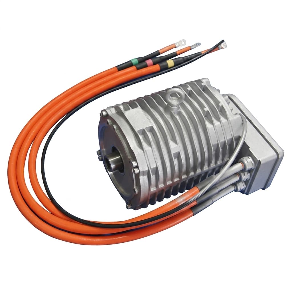
Matching SiC Inverters to Low-Inductance Coreless Axial Flux Motors: An Engineering Guide
Engineering guide for matching SiC inverters to low-inductance coreless axial flux motors, with ripple limits, choke options, RFQ checks, and sourcing questions.
When specifying advanced electric drive systems, engineering teams are increasingly adopting coreless (or ironless) Axial Flux Permanent Magnet (AFPM) motors. These motors offer high torque density, effectively zero cogging torque in the ideal coreless topology, extremely low rotor inertia, and strong power-to-weight ratios. Because they eliminate the heavy iron stator core, the coreless or yokeless AFPM motor topology is increasingly used in high-precision robotics, high-speed aerospace spindles, electric vertical takeoff and landing (eVTOL) aircraft, and specialized electric vehicle (EV) traction platforms.
However, procurement teams and systems engineers often encounter a severe and unexpected integration bottleneck: extremely low phase inductance.
Unlike traditional radial flux motors or even standard iron-core axial flux motors that use laminated steel stators, coreless AFPMs lack any magnetic iron core within their stator windings. This can result in phase inductances measured in the tens of microhenries ($\mu$H), rather than the typical millihenries (mH) seen in many conventional industrial motors. Driving a low-inductance motor with a standard, off-the-shelf Insulated-Gate Bipolar Transistor (IGBT) inverter can lead to excessive current ripple, severe rotor magnet heating, loss of efficiency, and premature controller faults unless the inverter, PWM frequency, and added inductance are validated as a system.
This comprehensive guide provides the technical framework for matching high-frequency Silicon Carbide (SiC) inverters to low-inductance AFPM motors, establishing strict boundaries for when to specify SiC, and providing actionable procurement criteria for engineering teams.
Executive Summary for Engineering Teams:
Coreless AFPM motors can exhibit ultra-low phase inductance, causing rapid current transients that many standard IGBT inverters, often operated near 10-16 kHz, cannot manage without added line inductance. The usual engineering path is a SiC (Silicon Carbide) MOSFET inverter designed for continuous high-frequency PWM, commonly in the 40 kHz to 100 kHz class for low-inductance motion systems. If budget constraints or legacy supply chains prevent SiC adoption, engineers must mathematically size and procure external high-frequency phase chokes to increase line inductance, then validate ripple current, rotor temperature, and insulation stress on a dynamometer.
Applicability note, updated 2026-07-20:
This guide is written for global OEM, robotics, aerospace, EV, and industrial teams evaluating 400 V to 800 V-class coreless AFPM drives where measured phase inductance is below roughly 100 $\mu$H. It is not a blanket rule for iron-core radial motors, iron-core axial flux motors, low-voltage MOSFET drives, or any drive already validated by the inverter supplier for the measured motor inductance and cable length. For RFQ review, prepare bus voltage, $L_d/L_q$, continuous and peak phase current, cable length, cooling method, and target switching frequency. Request a motor-inverter pairing review if those values are not yet reconciled.
1. The Physics of Low Inductance in Coreless AFPMs
To fully grasp the inverter matching challenge, we must revisit the fundamental electromagnetic relationship between applied voltage, phase inductance, and the resulting current transient.
The rate of change of current ($di/dt$) in any motor phase is governed by the fundamental differential equation:
$$ V_applied - E_bemf = L \cdot (di/dt) + R \cdot i $$
Where:
- $V_applied$ is the bus voltage applied by the inverter's Pulse Width Modulation (PWM).
- $E_bemf$ is the motor's Back Electromotive Force (BEMF) generated by the spinning magnets.
- $L$ is the phase inductance of the stator winding.
- $R$ is the phase resistance (usually negligible at high speeds).
- $di/dt$ is the instantaneous rate of change of current.
In a traditional motor equipped with a laminated steel stator core, the high magnetic permeability ($\mu_r \approx 4000$) of the silicon steel creates a massive phase inductance ($L$). This large $L$ acts as a crucial electrical buffer, effectively slowing down the rise and fall of current during each individual PWM pulse. The inverter can easily maintain a smooth sine wave.
In a coreless AFPM motor, the copper stator coils are potted in a non-magnetic epoxy resin, composite, or fiberglass structure. The relative permeability of this core is effectively that of free space ($\mu_r \approx 1$). Consequently, the phase inductance $L$ drops by two to three orders of magnitude. When the inverter switches on and applies full bus voltage across this microhenry-level inductance, the current spikes almost instantaneously.
The Current Ripple Crisis
If the inverter's switching frequency ($f_sw$) is too low, the ON-time of the PWM pulse is relatively long in the time domain. Combined with a massive $di/dt$ caused by the low $L$, the peak-to-peak current ripple ($\Delta I$) becomes massive before the inverter can turn the switch off.
Current Ripple: Low vs. High Switching Frequency in Low Inductance Motors
This high current ripple has three devastating, compounding consequences for the motor assembly:
- Massive Eddy Current Losses in Magnets: High-frequency ripple flux penetrates the metallic Neodymium (NdFeB) rotor magnets. Because the magnets are conductive, this changing flux induces massive eddy currents within the magnet material itself. This causes the magnets to rapidly heat up from the inside out, potentially crossing their Curie temperature and permanently demagnetizing the rotor—a catastrophic failure mode that is entirely driven by the inverter, not the mechanical load.
- Increased $I^2R$ Copper Losses: The RMS (Root Mean Square) value of the rippling current increases significantly compared to the smooth fundamental sine wave required for torque generation. This excess current generates zero useful torque but wastes massive amounts of energy as heat in the stator coils.
- Torque Ripple and NVH Degradation: The current ripple translates directly into electromagnetic torque ripple. This introduces high-frequency vibration and severe acoustic noise (NVH), completely defeating the smooth, cogging-free operational promise of the coreless architecture.
2. The SiC Inverter Solution
To suppress the current ripple to acceptable levels, the inverter's switching frequency ($f_sw$) must be increased drastically. By switching the transistors on and off much faster, the current is given significantly less time to rise and fall during each cycle, keeping the ripple tightly bound to the fundamental sine wave.
System Flow: SiC Inverter Integration
The Problem with Silicon IGBTs
Traditional Insulated-Gate Bipolar Transistors (IGBTs) are mature, reliable, and cost-effective. However, they suffer from inherently high switching losses. Every time an IGBT turns on or off, it transitions through a semi-resistive state, dissipating heat. If an engineer attempts to run a standard IGBT inverter at 50 kHz to control a low-inductance motor, the switching losses become so extreme that the IGBT modules will rapidly overheat and trigger a catastrophic thermal shutdown. Therefore, standard liquid-cooled IGBT inverters are practically capped at a switching frequency of around 10 kHz to 16 kHz.
Why Silicon Carbide (SiC) Often Becomes the Practical Choice
Wide-bandgap semiconductors, specifically Silicon Carbide (SiC) MOSFETs, possess dramatically lower switching losses and much faster electron mobility compared to standard Silicon.
- A properly designed SiC inverter can be specified for 40 kHz to 100 kHz-class PWM in low-inductance motor systems, provided the loss model, gate drive, cooling plate, and current measurement chain are all rated for that switching frequency.
- This high switching frequency is the direct physical antidote to low phase inductance. It limits the time that high bus voltage is applied across the un-buffered winding during each PWM cycle, reducing peak-to-peak current ripple before external chokes become necessary.
3. Engineering Comparison: SiC vs. IGBT for Coreless AFPMs
When drafting the procurement specification and system architecture, engineers must weigh the upfront capital cost of the SiC inverter against the operational efficiency, weight savings, and thermal survival of the motor.
| Specification / System Impact | Standard Silicon IGBT Inverter | Silicon Carbide (SiC) Inverter | Engineering Verdict for Coreless AFPM |
|---|---|---|---|
| Max Practical Switching Frequency | Commonly 10 kHz - 16 kHz in traction-class drives | 40 kHz - 100+ kHz-class designs are commercially realistic | Usually SiC. $\mu$H-level motor inductance often needs either higher PWM frequency or added line inductance. |
| Current Ripple ($\Delta I$) | Can become excessive without added inductance | Can be designed to single-digit ripple targets after validation | Validate waveforms. Rotor magnet temperature and RMS phase current are the acceptance criteria. |
| Inverter Efficiency at High RPM | Drops as switching frequency is pushed upward | Lower switching-loss devices support higher-frequency designs | SiC wins when high $f_sw$ is required. Confirm with a supplier loss map, not a brochure claim. |
| Hardware Procurement Cost | Baseline pricing and broad availability | Higher device and control-platform cost | Tradeoff. SiC can cost more upfront, but may avoid custom choke mass, enclosure space, and thermal rework. |
| Dead-Time Requirements | Often longer dead-time windows | Shorter dead-time settings are practical with suitable gate drive | SiC advantage. Lower dead-time can reduce harmonic distortion and improve zero-crossing behavior. |
| System Footprint & Weight | May require large external phase chokes | Can eliminate or minimize chokes | SiC advantage. Lower passive mass matters most in eVTOL, robotics, and compact vehicle packaging. |
4. Engineering & Procurement Decision Matrix
When sizing and procuring the inverter for your low-inductance coreless AFPM motor, system engineers and purchasing managers should evaluate the following dimensions to avoid project failure:
| Decision Factor / Specification | Evaluation Criteria | Supplier Communication / Inquiry Field | Risk of Failure / Neglect |
|---|---|---|---|
| Phase Inductance ($L_q, L_d$) | Is it < 100 $\mu$H? | "What is the minimum inductance your inverter can support at full bus voltage?" | Severe current ripple, rotor demagnetization, motor burning. |
| Switching Frequency ($f_sw$) | Requires $\ge 40$kHz | "Can the controller run at 40-100kHz continuously without thermal derating?" | Overheating of standard IGBTs, thermal shutdown. |
| Control Loop Bandwidth | $\ge 20$kHz execution | "What is the current loop execution rate of your MCU/DSP?" | Loss of control at high RPM, erratic torque response. |
| Dead-Time Configuration | $\le 1.0 \mu$s | "Is dead-time user-configurable in the firmware down to nanoseconds?" | High Total Harmonic Distortion (THD), zero-crossing distortion. |
| EMI / Cable Shielding | 360° Shielding Required | "Do you supply EMC-compliant glands and output filters for high $dv/dt$?" | Communication bus (CAN) corruption, sensor noise, failure of nearby electronics. |
| Thermal Protection Integration | PT100/PT1000 Support | "Does the firmware support active derating based on external stator temperature probes?" | Epoxy melting and short circuits in the coreless winding. |
| Lead Times & MOQ | SiC vs IGBT Availability | "What is the standard lead time for the SiC variant vs standard modules?" | Supply chain delays, project launch failure. |
Mid-stage sourcing CTA: Before releasing an RFQ, send the motor inductance, bus voltage, target switching frequency, and cable length to the inverter supplier and the motor vendor together. AFPM Motor can review those constraints against coreless stator winding options, phase choke sizing, and thermal sensor placement. Contact our application engineering team for a pairing review.
5. Procurement Checklist Before Releasing the RFQ
- Measure or request $L_d$ and $L_q$ at the relevant current, temperature, and rotor position; do not rely on a nominal catalog value alone.
- Define the maximum acceptable peak-to-peak current ripple as a percentage of fundamental phase current, then require the inverter supplier to show the PWM frequency and bus-voltage case used to calculate it.
- Ask the controller vendor for the minimum supported load inductance at full DC bus voltage and rated phase current.
- Require continuous switching-frequency, current-loop execution-rate, and thermal-derating data for the exact SiC or IGBT platform being quoted.
- Confirm whether external phase chokes, $dv/dt$ filters, common-mode chokes, or shielded motor cables are required at the planned cable length.
- Specify insulation requirements for the potted stator winding, including expected $dv/dt$, reflected-wave margin, and temperature-sensor type.
- Require a Factory Acceptance Test (FAT) report with phase-current ripple, inverter temperature, stator temperature, rotor/magnet temperature proxy, and fault log evidence.
6. The Alternative Approach: External Phase Chokes
What if your supply chain mandates the use of a legacy IGBT inverter platform, or your specific project budget cannot accommodate SiC semiconductor technology?
The only viable engineering workaround is to artificially increase the line inductance by placing three-phase external inductors (chokes) in series between the inverter outputs and the motor terminals. By adding, for example, a 50 $\mu$H or 100 $\mu$H choke to each phase, the total circuit inductance rises, allowing the slow 10 kHz IGBT inverter to control the current smoothly without triggering overcurrent faults.
The Severe Drawbacks of External Chokes:
- Weight and Volume Penalties: High-current phase chokes require very thick copper wire (to carry 100A - 500A traction currents) and heavy iron or powdered-alloy cores to prevent magnetic saturation. This added mass often completely negates the lightweight, compact advantage of choosing an axial flux motor in the first place.
- Financial Cost: High-quality, low-loss chokes capable of handling high traction-level phase currents without saturating are custom-engineered components, often expensive and difficult to source reliably.
- System Efficiency Degradation: The chokes inherently introduce their own $I^2R$ (copper) losses and magnetic core losses. This directly drops the total end-to-end powertrain efficiency, reducing battery range in EVs.
For stationary industrial applications (like heavy factory conveyors), massive chokes can be an acceptable compromise. For aerospace, eVTOL, drones, and high-performance automotive EVs, adding tens of kilograms of passive chokes is often unacceptable, making a validated SiC drive architecture the more practical path.
7. System Boundaries: When NOT to Specify SiC
While SiC is undoubtedly a revolutionary semiconductor technology, it is not universally required for all axial flux motors. It is a highly expensive over-specification if your specific motor architecture does not strictly demand it.
Do NOT blindly require SiC if:
- You are using a standard iron-core Radial Flux Motor. These inherently possess high inductance and are controlled perfectly by cheap 8-10 kHz IGBTs.
- You are using an iron-core Axial Flux Motor (where the stator utilizes slotted steel teeth). While some AFPMs are ironless, many use laminated silicon steel, SMC (Soft Magnetic Composite), or solid steel stators. These designs typically retain sufficient inductance for standard IGBT operation without massive ripple.
- The application operates at very low DC bus voltages (e.g., 24V-48V). At these low voltages, traditional low-voltage Silicon MOSFETs (not IGBTs) can already achieve high switching frequencies (up to 100 kHz) very efficiently and cheaply. SiC truly shines and becomes economically justifiable at 400V, 800V, and above.
8. Deep Dive: Voltage Reflection and Insulation Stress
Another crucial factor engineers must consider when transitioning to SiC is the stress placed on the motor's insulation. Because SiC MOSFETs switch on and off in mere nanoseconds, the $dv/dt$ (rate of change of voltage) is extreme—often exceeding 10 kV/$\mu$s.
When these ultra-fast voltage pulses travel down the phase cables to the motor, impedance mismatches between the cable and the motor can cause the voltage wave to reflect. This reflection phenomenon can double the voltage spike at the motor terminals. For a coreless motor operating on an 800V bus, the terminal voltage could momentarily spike to 1600V or higher during every single PWM cycle.
This severe voltage ringing places immense stress on the enamel insulation covering the copper stator wires. Over time, this can lead to partial discharge, corona effects, and ultimately, a catastrophic short circuit within the potted stator. To mitigate this, engineers must:
- Keep the phase cables between the SiC inverter and the motor as physically short as possible (ideally under 1 meter).
- Specify high-grade, corona-resistant, or double-coated magnet wire for the coreless stator winding.
- In extreme cases, utilize $dv/dt$ output filters on the inverter, though this again adds weight and cost.
9. Frequently Asked Questions (FAQ) for Buyers
Q: Can I just increase the PWM frequency on my existing IGBT inverter to 40kHz via software configuration?
A: No. While the software UI might allow you to type in "40kHz", the hardware switching losses will increase exponentially. The physical IGBT modules will quickly exceed their maximum thermal junction limits and the inverter will catastrophically fail or shut down within seconds under load.
Q: What is the typical lead time for custom SiC inverters compared to standard off-the-shelf IGBT drives?
A: Due to the high demand for SiC MOSFET modules in the EV sector, lead times for SiC inverters are generally longer, typically ranging from 12 to 24 weeks depending on the manufacturer. Engage with suppliers early in the prototyping phase and request sample allocations upfront.
Q: Will adding external phase chokes impact my product's warranty?
A: It depends on the motor manufacturer's specifications. If you add external chokes to force an IGBT inverter to work with a coreless motor, you must ensure the resulting ripple current stays below the motor's rated maximum. Always send your proposed choke/inverter schematic to the motor vendor for warranty validation.
Q: How do we test the motor-inverter pairing before full procurement?
A: Most premium motor and inverter suppliers offer a "matched pair" testing service on their dynamometers. You should request a Factory Acceptance Test (FAT) report showing the motor running at full load with the specific SiC inverter, verifying that rotor temperatures and phase currents remain within spec.
Q: What are the main communication fields we should include in our RFQ for SiC controllers?
A: Your RFQ must explicitly state: 1) The exact motor phase inductance (e.g., 35 $\mu$H), 2) The target switching frequency (e.g., 60 kHz), 3) Continuous and peak phase current, 4) Cooling medium and flow rate, and 5) Requested firmware parameters like dead-time adjustability.
Q: Are GaN (Gallium Nitride) inverters better than SiC for coreless axial flux applications?
A: GaN can switch even faster than SiC (easily exceeding 200 kHz) and is highly promising. However, for high-power, high-voltage traction applications (>400V, >50kW), SiC remains the more mature, robust, and commercially available technology.
10. Sources and References
To further explore the rigorous engineering literature on low inductance motors and wide-bandgap integration, refer to the following authoritative sources:
- Celera Motion / Novanta: Achieving Optimal Motion System Performance with Low Inductance Motors. Practical guidance on low-inductance motors, PWM frequency selection, and when additional series inductance is needed.
- University of Kentucky / IEEE Transactions on Industry Applications: Coreless Axial-Flux Permanent-Magnet Motor for Solar Cars. Academic comparison of coreless and conventional AFPM machines, including topology trade-offs relevant to lightweight vehicle drives.
- Infineon Technologies Community: Si to SiC Switch: When to Make the Move. Semiconductor supplier guidance on when SiC's switching-loss and high-frequency advantages justify moving away from silicon devices.
11. Consult Our Application Engineering Team
Matching the drivetrain architecture is absolutely critical to unlocking the true physical potential of axial flux technology. A mismatched inverter can turn a world-class motor into an overheating liability.
If you are struggling with inverter overcurrent faults, excessive rotor heat, or specifying the right wide-bandgap controller for a new AFPM platform, we can provide the necessary engineering support.
Contact our application engineering team to discuss integrated motor-inverter pairings, custom stator winding designs to carefully optimize internal inductance, or to procure complete direct-drive AFPM solutions precisely tailored for your project's voltage and switching frequency requirements.
Author

Categories
More Posts

Specifying Axial Flux Motors for 800V Architectures: Insulation & PD Risks
Learn how to specify 800V axial flux motors for SiC inverters: PDIV limits, VPI checks, insulation classes, and RFQ evidence to request from suppliers.
Foxconn & Magnax €35.5M Investment: Industrializing Yokeless Axial Flux Motors
Pan-International (Foxconn Group) invests €35.5M in Magnax to scale yokeless AFPM production. Discover the supply chain impact, risk factors, and engineering procurement actions.
Flat Wire vs. Round Wire Winding in AFPM Stators: Impact on Efficiency and Manufacturing
A quantitative analysis of flat (rectangular) copper wire versus round wire winding techniques in axial flux motors, covering fill factor, thermal performance, manufacturing cost, and OEM sourcing implications.