
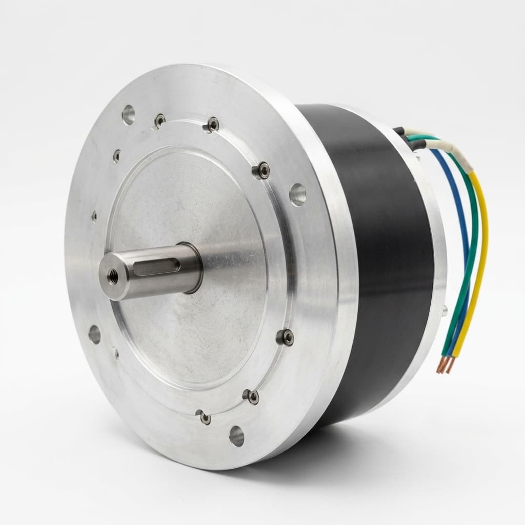
Stator Potting Resins for Yokeless AFPM Motors: Thermal Conductivity, Glass Transition (Tg), and Shear Torque Integrity
Compare stator potting resins for yokeless AFPM motors by thermal conductivity, Tg, adhesion, and process risk. Use the RFQ checklist to plan validation.
Stator potting resins for yokeless AFPM motors must be selected against the assembled motor's heat path and mechanical load path. A high thermal-conductivity number cannot establish tooth retention, and a high glass transition temperature (Tg) cannot establish fatigue life. Procurement teams need evidence for the exact formulation, production cure, bonded surfaces, and operating conditions before accepting a supplier's material recommendation.
In a yokeless segmented stator, removing the continuous stator back-yoke changes how reaction torque reaches the housing. Resin may transmit a substantial share of that load, alongside carriers, keys, retaining plates, or other mechanical features. Coreless stators have different coil-support needs and should not inherit a tooth-retention specification unchanged. Start by identifying what the potting actually supports in your design.
Quick sourcing answer: Shortlist a resin only when the supplier can connect thermal conductivity, temperature-dependent stiffness, adhesion, and filling behavior to the same production process. Compare qualified material-and-process combinations, rather than ranking resin families by one datasheet value.
Scope and review date — November 10, 2026: This English-language guide is for global OEM procurement, motor design, and supplier quality teams evaluating yokeless AFPM stator encapsulation. It provides a qualification framework and explicitly hypothetical calculations, not measured AFPM Motor test results, a voltage rating, or automotive/aerospace certification. Final limits depend on the motor geometry, cooling, insulation system, mission profile, and applicable customer requirements.
If you already have a stator drawing and duty cycle, request an engineering review with the proposed resin grade and cure schedule. The checklist below identifies evidence to request before that discussion.
1. The Mechanics of Yokeless Stator Torque Transmission
In a dual-rotor, single-stator yokeless AFPM motor, discrete wound teeth sit between the rotor discs. Tooth material, support geometry, and cooling arrangements vary. Do not assume that all designs transfer torque exclusively through adhesive bonding, or that resin alone provides adequate axial restraint.
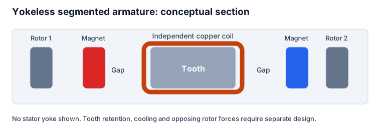
Worked torque screen: total force versus force per tooth
For an illustrative stator with 400 N·m reaction torque and an assumed effective force radius of 0.100 m:
- Total equivalent tangential force:
F_total = T / r_eff = 400 / 0.100 = 4,000 N. - With 18 teeth and an assumed equal load share:
F_tooth = 4,000 / 18 ≈ 222 N. - If the effective shear area per tooth is an assumed 200 mm²:
tau_average = 222 / 200 ≈ 1.11 MPa. - At an assumed transient torque of 800 N·m, these equivalent forces and average shear stress double.
These are equilibrium calculations with invented inputs, not an allowable stress or joint rating. The effective radius must represent the actual electromagnetic force distribution; the arithmetic midpoint of the active radii is only an approximation. The 4,000 N value is the equivalent force for the whole stator, not the force on each tooth. Equal load sharing also neglects electrical torque ripple, manufacturing variation, and local stiffness differences.
An average shear calculation cannot resolve edge stresses, peel loading, tooth tilt, or resin creep. Ask the mechanical designer to identify the bonded area, mechanical interlocks, unsupported spans, and axial load cases. Then compare a temperature-dependent structural model with representative joint and assembly tests. The useful output is a documented deformation and strength margin against the actual airgap budget, including rotor runout and thermal movement.
A room-temperature lap-shear number from a metal coupon is a screening input. It does not describe the strength of a curved tooth joint bonded to coated laminations, SMC, or wire enamel after fluid aging. Specify the substrate, surface treatment, bond thickness, temperature, loading direction, and observed failure mode for each test.
2. Glass Transition (Tg): Use the Modulus Curve, Not a Universal Cliff
A thermoset's glass transition occurs over a temperature region. Its stiffness and expansion behavior can change substantially through that region, but crossing a quoted Tg does not prove instantaneous motor failure. The outcome depends on retained modulus, load duration, creep, load sharing, and the mechanical support arrangement. Equally, operation below Tg does not by itself prove a safe joint.
ASTM E1640 describes assigning Tg using dynamic mechanical analysis (DMA) and explains that the reported value depends on the measurement technique. For structural potting, obtain the storage-modulus curve across the relevant temperature interval and identify how the supplier assigned Tg.
DSC versus DMA: make supplier reports comparable
Differential scanning calorimetry (DSC) detects a heat-capacity change. DMA measures viscoelastic response under specified dynamic conditions. Storage-modulus onset, loss-modulus peak, and loss-factor peak are different reporting conventions. There is no universal temperature correction that converts a supplier's DSC Tg into the onset of mechanical softening.
Request the test method, frequency, heating rate, specimen preparation, moisture conditioning, and cure history. A fully post-cured laboratory coupon can differ from resin in a thick stator section that followed a shorter production cycle. Verify the proposed cycle on representative material and keep the formulation revision traceable.
Set the operating margin from the local resin temperature and required stiffness throughout the duty cycle. The winding hotspot, coolant inlet temperature, and temperature at a loaded resin web are different quantities. As an illustrative purchasing screen, a team might compare a 130 °C local resin temperature with a 155 °C DMA onset, giving a nominal 25 °C separation. That subtraction is not a standard or an approval rule: transient loads, aging, model uncertainty, and creep may require a different margin.
3. Thermal Conductivity versus Filling Quality
Conductive fillers can improve heat transfer through a polymer while changing viscosity, density, settling behavior, and tool wear. Filler type alone does not determine the finished material properties. Particle shape and size distribution, loading, resin chemistry, and cure all matter. Compare the cured compound's measured conductivity, not the conductivity of the filler powder.
Wevo's electric-motor encapsulation overview describes epoxy- and silicone-based compounds combining thermal management with process flow and electrical insulation. It supports considering those properties together; it does not supply a universal AFPM structural rating or an interchangeable resin specification.
For each candidate, request conductivity test method, measurement direction, temperature, and cure condition. Compare mixed viscosity at the intended dispensing temperature and at a defined time after mixing. A low initial viscosity is of little use if the material gels before the last narrow passage fills. Heating can improve flow while shortening usable processing time, so establish the complete filling window.
Worked thermal screen: thickness can outweigh conductivity
For a simple one-dimensional slab, R_th = L / (k × A). Assume a 1 mm resin layer, conductivity of 2 W/(m·K), and effective area of 0.01 m². The layer resistance is 0.001 / (2 × 0.01) = 0.05 K/W. If 200 W passes through that layer, its calculated temperature drop is 10 K. Doubling thickness to 2 mm doubles that layer's resistance and temperature drop, with all other inputs held constant.
These hypothetical values illustrate sensitivity; they do not predict a complete winding hotspot. The calculation excludes three-dimensional spreading, winding insulation, interface resistance, coolant convection, and parallel heat paths. Use it to question unnecessary resin thickness, then validate the assembled thermal network with representative loss and cooling conditions.
A high bulk conductivity cannot compensate reliably for poor wetting or disconnected thermal paths. Voids can increase local thermal resistance and affect electrical stress, but location and shape matter as well as total void volume. Inspect critical regions with a method whose resolution and detection limits are documented. Do not infer a universal permissible void diameter or discharge lifetime from the DC bus voltage alone.
4. CTE Mismatch, Adhesion, and Thermal Cycling
Copper, core materials, aluminum housings, coatings, and cured resin expand differently with temperature. Cure shrinkage adds another source of residual strain. A screening expression is delta_strain = (alpha_resin − alpha_substrate) × delta_temperature. It estimates differential free expansion for specified coefficients; it is not a general formula for interfacial shear stress.
For an explicitly hypothetical difference of 20 × 10⁻⁶/K across a 100 K temperature change, the differential free strain is 0.002, or 0.2%. Actual joint stress also depends on constraint, geometry, viscoelastic relaxation, cure history, and temperature gradients. A detailed model or representative test is needed before comparing stress with an adhesive strength limit.
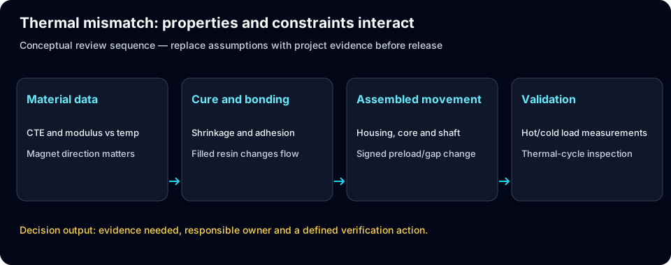
Fillers, tougheners, primers, cleaning, and surface activation are possible design tools. Their effects must be demonstrated on the actual substrate and formulation. Do not assume that toughening preserves Tg unchanged, or that a primer compatible with bare metal is compatible with wire enamel and core coatings. Document permitted handling time between surface preparation and casting.
Agree thermal-cycle temperatures, dwell times, transition rates, cycle count, and inspection methods with the customer. A cycle profile for one vehicle installation does not automatically qualify another application. Inspect retained strength, insulation behavior, and dimensional movement after cycling, rather than accepting visual appearance alone. Fluid exposure and moisture conditioning should reflect the real coolant, lubricant, and operating environment.
5. Resin Selection Matrix: Evidence to Compare Before an RFQ Award
This matrix defines comparable questions instead of presenting unsupported property ranges for entire chemistry families. A candidate with an unknown safety-critical property remains unqualified, even if other datasheet values look attractive.
| Selection criterion | Evidence to request | Yokeless AFPM decision |
|---|---|---|
| Thermal conductivity | Cured-grade result with method, direction, and temperature | Evaluate the complete coil-to-coolant resistance |
| Tg and stiffness | DMA curve and Tg convention for the production cure | Check retained stiffness at loaded resin temperatures |
| Creep and fatigue | Temperature-dependent tests with load duration and conditioning | Establish allowable long-term tooth movement |
| CTE and cure shrinkage | Expansion data over the operating interval and shrinkage information | Model mismatch with housing, core, and winding |
| Adhesion | Representative substrate tests, surface preparation, and failure modes | Verify the actual load-transfer interface |
| Electrical insulation | System-level insulation and discharge evidence under agreed conditions | Match inverter waveform, environment, and insulation architecture |
| Mixed viscosity and working time | Time-temperature flow data and representative fill trials | Confirm narrow passages fill before gelation |
| Void detection | Inspection method, resolution, locations, and sampling plan | Control defects where thermal and electrical stresses matter |
| Fluid and moisture resistance | Aging data for the named fluids and exposure conditions | Verify retained mechanical and dielectric properties |
| Production and commercial control | Lot traceability, change notification, yield, and processing cost | Compare accepted stator cost and requalification exposure |
How to shortlist chemistry families
A filled epoxy is a candidate when a relatively stiff load path is required, but its hot strength, toughness, and adhesion remain grade-specific. A polyurethane may offer a different balance of compliance and processing behavior; do not infer its structural suitability from the chemistry name. Silicone can suit thermal and environmental encapsulation when an independently validated mechanical carrier provides retention. Its compliance must be included in any load-bearing assessment.
Alumina- and boron-nitride-filled formulations should be compared as specific grades under the same conditions. Do not assign fixed cost multipliers, temperature limits, or allowable power classes to those filler families. Ask suppliers to price the material consumption, dispensing losses, equipment needs, cure, inspection, and expected scrap separately. A more expensive resin can reduce accepted-part cost, but only a documented process comparison can establish that result.
For build-to-print support, the AFPM stator and rotor assembly program is a relevant discussion route. Send the load-path drawing and the evidence matrix with the inquiry so that responsibilities and missing data can be identified early.
6. Manufacturing Processes: VPI, Vacuum Casting, and APG
The resin and process need joint qualification. Vacuum pressure impregnation (VPI) generally targets penetration of winding insulation spaces; it should not be assumed to create a dimensionally controlled structural casting. Vacuum casting uses tooling to define the encapsulated geometry. Automated Pressure Gelation (APG) uses controlled filling and pressure during gelation. Each route has formulation and tooling constraints.
Pressure-assisted processing may help feed material as shrinkage occurs, but it does not make a casting stress-free or guarantee a particular void fraction. Likewise, a vacuum cycle cannot establish complete wetting without representative evidence. Fill passages, vents, degassing, temperature, mixture ratio, gel timing, and tool release all influence the result.
Nagel's Lambda Resins production overview describes structural casting for axial-flux stators and integration of material with production equipment. This is a supplier account supporting the need for combined material-and-process development. It is not independent validation of a particular AFPM Motor production line, universal APG adoption, or guaranteed throughput.
Ask for a representative fill trial before committing tooling investment. Record material lot, mix ratio, component temperatures, vacuum and pressure history, fill time, cure profile, and critical dimensions. Section pilot pieces or use suitable non-destructive inspection to compare the predicted filling pattern with the result. Use instrumented trials where exotherm is a concern: oven or mold setpoint alone does not establish the resin's internal peak temperature.
Compare cycle time including preparation, preheating, filling, cure, post-cure, demolding, inspection, and cleaning. A quoted injection time is not the accepted-stator production rate. For scale-up planning, AFPM OEM manufacturing support can be used to discuss scope and feasibility; specific equipment, capacity, and qualification evidence must be agreed for the project.
7. Quality Gate and Sourcing Checklist for Stator Encapsulation
Use the following open checklist in an RFQ review. The boxes are intentionally unchecked: this article cannot establish that a supplier has passed them. Assign an owner and an agreed acceptance criterion to every item before pilot release.
- Material identity and cure: Record resin and hardener grade, formulation revision, shelf life, storage, mixing ratio, cure, and permitted post-cure. Require change notification.
- Thermal and DMA evidence: Obtain conductivity results and temperature-dependent modulus for representative cured material. Reconcile test conventions before comparing suppliers.
- Mechanical load path: Define torque, transient duration, axial force, bonded areas, carriers, keys, and permissible displacement. Validate representative joints hot and after aging.
- Fill and void control: Agree critical inspection regions, detection resolution, sampling, and defect disposition. Retain fill-trial records and correlate inspection with destructive sections where needed.
- Thermal cycling: Agree the application-specific profile and verify retained strength, insulation, and airgap-related dimensions after exposure. A standard's name alone is insufficient evidence.
- Electrical insulation: Define insulation-system type, inverter waveform, cable effects, temperature, pressure/altitude, and test method. Agree whether partial-discharge testing is required and which checks belong at qualification or end of line.
- Chemical compatibility and surfaces: Test the actual coolant or oil and representative coated substrates. Record cleaning, activation, primer, and handling limits.
- Production release: Agree process control limits, traceability, nonconformance handling, sample retention, and requalification triggers. Separate pilot acceptance from serial-production approval.
A generic dielectric-strength result in kV/mm does not establish motor PDIV, a voltage class, or insulation life under repetitive inverter pulses. Similarly, a successful room-temperature push-out test does not establish hot fatigue life. The AFPM quality validation page provides a route for discussing the evidence plan, without implying that every listed test is standard equipment or an existing certification.
8. Frequently Asked Questions
Can a potted yokeless AFPM stator be repaired or rewound?
Structural encapsulation often makes coil replacement difficult and potentially destructive. Repairability depends on segmentation, resin removal methods, accessible interfaces, and the manufacturer's approved repair process. Do not assume either universal repairability or universal scrap. Agree inspection before potting, repair restrictions, and disposition of failed assemblies. Estimate production fallout from pilot records rather than using an invented industry scrap percentage.
Can silicone replace structural epoxy to reduce thermal stress?
Possibly, if the design provides and validates a suitable mechanical retention path. A compliant encapsulant may relieve some mismatch stress while allowing more movement. That tradeoff can be unacceptable where potting is expected to hold teeth in position. Review hot stiffness, assembly deflection, and fluid compatibility for the exact grade; neither a chemistry label nor thermal resistance alone answers the retention question.
Is the highest-conductivity resin always the best choice?
No. A higher conductivity can reduce one component of thermal resistance, while increased viscosity or poor wetting can undermine the assembled path. Compare the same geometry, filling process, cure, and cooling conditions. Use a conductivity improvement to update the thermal model, then check whether the resulting process and structural properties remain acceptable.
How much margin below Tg is required?
There is no universal AFPM margin. Start from local resin temperature, retained modulus, creep behavior, load duration, conditioning, and model uncertainty. Define the Tg test convention and production cure first. A nominal temperature separation can be an early screen, but assembly testing and the required displacement/strength limits determine acceptance.
What causes cracking during cure?
Potential contributors include exotherm, uneven cure, shrinkage, geometric constraint, contamination, and poor adhesion. Record internal resin temperature and actual process conditions before selecting a remedy. A slower or staged cure may help one formulation while leaving another under-cured; obtain the formulator's approved processing window and verify it on representative sections.
9. Next Steps for Powertrain Sourcing and Engineering Teams
Create a short decision record containing the proposed formulation, production process, load-path drawing, temperature map, and qualification evidence. List unknowns alongside the party responsible for resolving them. A useful shortlist distinguishes candidates ready for representative trials from candidates supported only by a room-temperature datasheet.
Before award, resolve how each critical claim will be checked on the same material-and-process combination. Before serial release, confirm that the approved evidence remains representative of tooling, batch size, surface preparation, and cure conditions. Revisit qualification when formulation, substrate coating, coolant, tool geometry, or thermal duty changes.
Planning a yokeless AFPM program? Contact AFPM Motor engineering with your torque-speed duty cycle, cooling conditions, available envelope, proposed stator support, and candidate resin data. Use the checklist to agree a focused evidence plan and manufacturing feasibility review; prototype and production commitments require project-specific confirmation.
Sources and References
Sources checked November 10, 2026. The calculations and decision framework above are illustrative engineering analysis, not first-party laboratory evidence. Manufacturer publications describe their own materials or processes and do not qualify another supplier's assembly.
- ASTM International — E1640: Glass transition temperature by dynamic mechanical analysis. Official method overview supporting the discussion of DMA, the transition region, and method-dependent Tg reporting. The complete test procedure requires the applicable standard.
- Wevo — Products for smart thermal management in electric motors. Manufacturer overview supporting combined consideration of heat transfer, insulation, flow, and material compatibility. It supplies no universal yokeless-stator structural limits.
- Nagel Technologies — Producing axial flux motors economically: Lambda Resins material and process innovation. Supplier publication dated May 15, 2025, supporting structural stator casting and integrated process development. Its performance claims are not adopted here as guaranteed outcomes.
Author

Categories
More Posts
High-Speed Axial Flux Rotor Magnet Retention: Carbon Fiber Sleeves, Hoop Stress & Tip Speed Limits
Compare high-speed axial flux rotor magnet retention, carbon fiber sleeves, hoop stress and thermal fit. Use the RFQ checklist to define qualification evidence.
NdFeB Magnet Grades in Axial Flux Motors: A Cost and Temperature Specification Guide for Buyers
Use this procurement guide to compare NdFeB magnet grades for axial flux motors, SH/UH/EH temperature limits, Dy/Tb cost drivers, and supplier checks.
Rotor Position Sensor Selection for Axial Flux Motors: Hollow-Shaft Resolvers, Inductive Rings, and Magnetic Encoders under High Pole Counts and Axial Runout
Compare rotor position sensors for axial flux motors: resolvers, inductive rings, and magnetic encoders. Define error and runout budgets, then plan your OEM RFQ.