
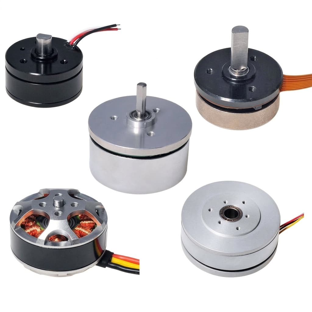
Rotor Position Sensor Selection for Axial Flux Motors: Hollow-Shaft Resolvers, Inductive Rings, and Magnetic Encoders under High Pole Counts and Axial Runout
Compare rotor position sensors for axial flux motors: resolvers, inductive rings, and magnetic encoders. Define error and runout budgets, then plan your OEM RFQ.
Executive summary for procurement and powertrain engineering: Rotor position sensor selection for axial flux motors starts with the electrical angle error budget, the available bore and axial space, and the complete signal delay. Shortlist a hollow-shaft resolver when environmental robustness and an existing resolver interface are priorities; shortlist a PCB inductive ring when a thin, magnet-free target suits the package. Retain magnetic encoders where measured fringe fields and temperature permit, and optical encoders where a protected, clean cavity is available. High pole counts amplify mechanical angle error, but neither motor topology nor sensor technology alone establishes an acceptable accuracy, runout, or safety rating.
Reviewed and updated: 07 November 2026. Scope: English-language design screening for global OEM engineering and procurement teams working on AFPM synchronous motors. The examples below are reproducible calculations using stated assumptions, not physical test results or catalog guarantees. Automotive safety targets follow the application hazard analysis; aviation requires its own certification basis. This guide does not certify an assembly for either application. Revisit the selection when pole count, bearing arrangement, speed, cooling fluid, or inverter timing changes.
For an architecture review, bring your motor drawing and controller requirements to our AFPM Motor OEM Manufacturing team. Use AFPM Quality Validation to define the evidence needed before approving a supplier.
1. The Geometry and High-Pole-Count Challenge in AFPM Sensing
A short axial motor can leave little room for an end-shaft encoder. A through-bore may carry a half-shaft, cooling passage, or actuator mechanism, making a ring sensor attractive. However, AFPM geometry does not rule out a solid-shaft sensor: a closed-center machine with spare end-bell space may accommodate one economically. Start with the actual shaft, bearing, and housing drawing rather than a preferred sensing technology.
Specify the usable inner and outer diameters, mounting datums, cable exit, service access, and the complete axial stack. The stack includes target thickness, operating clearance, PCB or resolver body, connector, fasteners, and insulation. Comparing only the sensing IC package or bare PCB thickness can hide the largest integration costs.
For a motor with p pole pairs, mechanical angle error becomes electrical angle error:
Δθe = p × Δθm
p = total magnetic pole count / 2
Consider a calculation example, not a typical motor rating: a 32-pole motor has p = 16. A mechanical offset of 0.125° therefore produces 2.0° electrical error. A 24-pole motor has 12 pole pairs, so a 0.1° mechanical shift produces 1.2° electrical error. Distinguish poles from pole pairs in every RFQ and acceptance report.
The consequence also needs proportion. For a nonsalient permanent-magnet motor, fixed current magnitude, and an intended zero direct-axis current, a simplified static model gives:
Torque retention ≈ cos(Δθe)
Unintended direct-axis current magnitude ≈ Is × |sin(Δθe)|
At 3.6° electrical error, the model predicts about 99.80% torque retention and 6.28% of current magnitude on the unintended direct axis. Total copper loss does not automatically rise at fixed current magnitude. Maintaining the original torque requires slightly more current; large offsets, periodic errors, saliency, and field weakening require a fuller drive model. The sign of direct-axis current depends on the offset convention. A small constant error alone does not prove severe ripple, overheating, or demagnetization.
If a project allocates 1.0° electrical error entirely to mechanical position error at p = 16, the equivalent allowance is 0.0625° mechanical. In practice, calibration residuals, thermal drift, quantization, mounting errors, and timing error must share the system budget. Define whether the budget is peak, peak-to-peak, or statistical. Do not combine worst-case terms by root-sum-square unless their independence and distributions are justified.
Rotor Position Sensor Integration & Stray Field Interfaces in an Axial Flux Motor
Figure 1: Conceptual AFPM sensor packaging schematic, not to scale. The sensor options are alternatives; target attachment, clearances, and axial movement must be defined on the assembly drawing. This illustration is not a measured field map or a tested motor configuration.
2. Sensor Architecture Comparison: Resolvers vs. Inductive vs. Magnetic vs. Optical
Procurement should compare installed systems under the same operating conditions. Resolution is the smallest reported increment; accuracy describes closeness to the true angle; repeatability describes consistency. A high bit count cannot compensate for target eccentricity or an incorrect electrical zero.
A. Hollow-Shaft Variable Reluctance Resolvers
A VR resolver uses a shaped magnetic rotor and wound stator to produce angle-dependent AC signals. Tamagawa's resolver overview describes analog two-phase outputs and the environmental robustness of the iron-core-and-coil construction. Obtain a model-specific drawing and rating before choosing a bore, temperature limit, excitation frequency, or resolver-to-digital converter (RDC).
Resolvers can be attractive when the inverter already supports excitation and tracking conversion. Include the RDC, harness, shielding, excitation power, and assembly alignment in the cost comparison. A multi-speed resolver reports several cycles per mechanical revolution; it does not inherently remove mounting error, converter error, or the need to establish sector identity when full-turn absolute position matters.
B. PCB Inductive Eddy-Current Sensors
These sensors use stationary transmit/receive coils and a rotating conductive target. They suit hollow-bore layouts and avoid a dedicated target magnet. For one concrete interface example, TI's LDC5072-Q1 provides analog sine/cosine signals. Its stated excitation band is 2.4–5 MHz, and its operating ambient range is −40°C to +160°C. Those are IC specifications, not approval of the target, PCB, connector, or finished motor.
The complete design still needs coil geometry, target material and thickness, minimum clearance, electronics placement, and EMC validation. A digital interface such as BiSS-C requires a suitable encoder implementation; an inductive front-end alone does not imply serial absolute output. Temperature limits depend on every assembly component, not only the laminate glass-transition temperature.
C. Off-Axis Magnetic Ring Encoders
A multipole magnetic ring and one or more readheads can provide a compact, economical arrangement. The output may be incremental or absolute depending on track encoding and electronics. Evaluate the desired target field together with the motor fringe field at the readhead throughout rotor position, phase current, and temperature.
Susceptibility depends on the particular Hall or magnetoresistive sensor, field direction, differential geometry, magnet grade, and installation. Neither a universal saturation threshold nor a universal shielding thickness follows from the technology name. Magnetic encoders remain candidates when the assembled system meets its error and diagnostic limits. Confirm magnet aging and retention at the specified temperature rather than assuming all rings lose polarization above one temperature.
D. Hollow-Shaft Optical Encoders
Optical ring encoders can offer fine resolution and avoid magnetic interference at the sensing element. Their suitability depends on the scale, readhead, sealing, contamination control, shock, and temperature ratings. An exposed optical track is a poor fit for oil mist or debris; a qualified sealed implementation may still be viable. Do not treat the whole technology as unsuitable for every traction application.
The following matrix is a selection framework, not a table of guaranteed numerical performance. Request the missing values on supplier drawings and test reports.
| Sourcing and engineering metric | Hollow-shaft VR resolver | PCB inductive ring | Off-axis magnetic ring | Optical ring encoder |
|---|---|---|---|---|
| Installed axial stack | Wound assembly plus mounting and clearance | PCB, target, gap, electronics and mounting | Ring, readhead and any field separation | Scale, readhead and protective enclosure |
| Bore and target attachment | Model-specific lamination and hub geometry | Custom coil and target geometry possible | Ring diameter and retention constrain layout | Scale diameter, hub and readhead access constrain layout |
| Axial float and tilt | Verify coupling and residual angle error | Common gain changes may cancel; tilt may not | Check field amplitude and angle over travel | Check focus, track alignment and signal margin |
| Motor fringe-field exposure | Evaluate magnetic-core bias and EMC | Magnet-free principle; validate complete assembly | Measure intended and stray fields together | Optical principle avoids magnetic pickup; electronics still need EMC checks |
| Temperature and fluids | Rate winding, potting, leads and connector | Rate IC, PCB, coating, adhesive and target | Rate readhead, magnet and retention system | Rate emitter, detector, scale and seals |
| Interface and processing | Excitation, analog signals and RDC | Front-end-dependent; analog or additional conversion | Product-dependent incremental or absolute output | Product-dependent incremental or absolute output |
| Startup observability | Check resolver speed ratio and angle ambiguity | Check target periods and absolute-sector information | Check track encoding and required startup motion | Check absolute encoding or index procedure |
| Cost and lifecycle evidence | Quote resolver, RDC, harness and tooling | Quote coil development, target tooling and calibration | Include field management and ring magnetization | Include cleanliness, sealing and alignment |
For a useful quotation, request the same drawing revision, quantities, environmental envelope, test conditions, and calibration responsibilities from every supplier. A cheaper bare sensor may require a more expensive bearing arrangement or end-of-line station.
3. Dynamic Axial Runout, Disc Float, and Airgap Modulation
Distinguish axial end float (translation along the shaft), face runout (variation during rotation), disc bending, tilt, and radial eccentricity. Each moves the sensor target differently. The sensor gap is separate from the motor's electromagnetic working airgap; measure it at the sensor track and its mounting datum.
Bearing preload changes, differential thermal expansion, external thrust, and magnetic attraction can alter the gap. Their magnitudes depend on the assembly. Record the cold, hot, loaded, and overspeed clearance cases rather than assigning an AFPM-wide float range. Preserve a positive minimum clearance after tolerances, deflection, and assembly variation are combined.
After carrier demodulation, an ideal matched sine/cosine pair can be written as:
S = A(z) × sin(N × θm)
C = A(z) × cos(N × θm)
φ = atan2(S, C) = N × θm, modulo 360°
Here N is the number of sensor cycles per mechanical revolution; it is not automatically the motor pole-pair count p. If N = p and polarity and zero are calibrated, the pair can represent commutation angle directly. Otherwise, the controller must recover mechanical angle or resolve the necessary sector before scaling it to motor electrical angle. A repeated track alone does not establish full-turn absolute position.
Common amplitude variation cancels in this ideal ratio. Real offsets, unequal gains, harmonic distortion, tilt, and target asymmetry leave residual error; the angle also becomes unreliable if signal amplitude falls into noise or diagnostics report a fault. Both single-ended and differential sine/cosine interfaces can use ratiometric angle recovery. Differential signaling improves rejection of common-mode electrical interference; it does not guarantee mechanical error cancellation.
For qualification, sweep the allowed axial gap, radial offset, and tilt independently, then test their worst combinations across temperature and speed. Compare angle against an independent reference with a known uncertainty. Log peak angle error, minimum signal amplitude, diagnostic status, and any dropout. A claimed gap tolerance is useful only when its associated accuracy and test conditions are stated.
4. Stray Magnetic Flux: Measure at the Readhead
Rotor fringe flux and current-dependent fields are relevant to sensor placement, but a magnet's remanence is not the field at the sensor cavity. Map the local field vector at candidate locations using a suitable probe and/or a validated electromagnetic model. Include rotor-angle variation, maximum phase current, cold magnets, and nearby steel structures.
For a magnetic ring encoder, ask the supplier for the permitted external field magnitude and direction relative to the useful target field. Test the final ring, readhead, bracket, and harness together. Moving the readhead, changing its orientation, or adding a designed ferromagnetic shield may help. Shield material, saturation, seams, and manufacturing variation affect performance; choose dimensions from analysis and measurement rather than a generic wall thickness.
Inductive sensing avoids reliance on a target magnet and can reduce this integration problem. It still needs tests for switching interference, conductive debris, nearby metal, supply disturbance, and cable coupling. A resolver's magnetic core can be biased by strong external DC fields. An aluminum end bracket does not provide effective shielding against a static magnetic field. Do not accept an untested assembly solely because its sensing carrier is AC.
5. Inverter Signal Latency, Interfaces, and Functional Safety
Position accuracy must include the age of the angle used by the control loop. For a worked example with 8,000 RPM, p = 16, and 10 µs uncompensated delay:
Electrical frequency fe = RPM × p / 60 = 2,133.3 Hz
Electrical period = 1 / fe = 468.75 µs
Angle lag = 360° × fe × delay = 7.68° electrical
The calculation is independent of sensor technology. Define the complete chain: sensing, filtering, conversion, transport, scheduling, and PWM actuation. Count delays once; distinguish a timestamped sample from the time a packet finishes arriving. Repeatable delay can be compensated using speed prediction, while jitter and acceleration introduce residual error. If the timing allocation is 1.0° electrical at this frequency, the equivalent uncompensated delay allowance is about 1.30 µs.
Analog vs. Serial vs. Incremental Feedback
Analog sine/cosine is continuous but has finite front-end, filtering, ADC, and RDC delay. Serial transmission adds protocol and implementation timing; compare the sample timestamp, clock rate, payload length, update interval, and integrity checks. BiSS-C and SSI do not universally provide the same diagnostics or CRC behavior. Incremental A/B/Z feedback needs a startup reference or another method to establish absolute commutation angle; UVW signals provide coarse electrical sectors.
A lifecycle caution is useful here: Renesas lists IPS2200 as an industrial inductive sensor with sine/cosine outputs and programmable propagation delay below 10 µs, but currently marks it obsolete. It is a technical reference here, not a recommended new-design purchase. Request current lifecycle status, change-notification terms, and a qualified replacement plan for every shortlisted part.
For controller integration and timing review, use AFPM Motor Controller Tuning alongside the sensor supplier's interface documentation. Verify timing under the actual inverter configuration before freezing the RFQ.
Functional Safety Boundaries
ISO 26262-1:2018 is Part 1: Vocabulary for road-vehicle functional safety; it is not Part 10, an aviation standard, or proof that a sensor is certified. Select the applicable safety requirements through the system hazard analysis, then request the relevant safety manual, failure analysis, diagnostics, independence assumptions, and fault-response evidence.
For example, TI states different systematic and hardware capability limits for LDC5072-Q1: up to ASIL C(D) systematic capability and ASIL C hardware capability. This is not blanket ASIL-D approval of an inductive sensor assembly. Two channels may share a target, supply, bracket, or environmental fault. Evaluate those common causes and the inverter's response as part of the system architecture.
6. End-of-Line Electrical Zero Calibration
The controller needs a defined relationship between the sensor reference and the rotor magnetic axis. For a single-turn mechanical-angle sensor, one possible convention is:
θe = p × θm − θoffset, modulo 360°The sign, phase sequence, rotation direction, and angle origin must match the controller. For a multi-period sensor, document the mapping described in Section 3 instead of blindly applying the mechanical-angle equation.
Back-EMF Reference Alignment
An external drive can spin the unpowered motor while a synchronized measurement captures sensor angle and phase back-EMF. Extract a defined fundamental reference and compare it with the sensor. Line-to-line and phase-to-neutral voltage have different phase relationships; filtering and acquisition delay also shift the apparent crossing. A phase-voltage zero crossing is not universally the rotor direct-axis zero. Document the transformation used by the drive's convention, reference uncertainty, test speed, and repeatability.
Static Current-Vector Alignment
A controlled stator current vector can align a freely moving rotor while its sensor reading is recorded. Define current and duration from thermal limits and available torque; remove external loads where possible. Friction, cogging, cable forces, and constrained motion can bias the result. Repeat from both directions and quantify uncertainty. This method can be acceptable when it meets the allocated error budget; it has no universal accuracy or universal prohibition in traction drives.
Offset Storage and Acceptance
Store the offset with motor serial number, pole-pair count, sensor ratio, firmware convention, calibration temperature, and revision. Protect integrity and define which record is authoritative if both motor and inverter store values. After sensor replacement, target adjustment, or bearing work, require recalibration unless interchangeability has been demonstrated.
Confirm direction and phase sequence at controlled current, then check residual angle error across the required speed and temperature range. A valid stored number does not prove a correct mapping. Agree acceptance and rework procedures before pilot production.
7. OEM Procurement and Engineering Qualification Checklist
Use this checklist to request project-specific evidence, not to impose unvalidated universal limits:
- Mechanical envelope: Release bore, outer diameter, installed axial stack, fastener and connector access, datums, and minimum moving clearance on an assembly drawing.
- Electrical angle budget: State pole count and pole-pair count separately. Allocate peak residual error across sensor, mounting, calibration, temperature, and timing at specified operating points.
- Runout and gap: Define nominal/minimum/maximum gap, axial travel, face TIR measurement radius, radial offset, and tilt; require residual error and dropout results over those conditions.
- Fringe fields and EMC: Provide the field map and inverter switching conditions. Require accuracy and diagnostic behavior with the intended target and final harness.
- Thermal and fluid exposure: Rate the complete sensor assembly and test representative fluids, soak duration, thermal cycles, vibration, and contamination. Motor insulation class does not set sensor ambient capability; an IP rating alone does not prove oil compatibility.
- Interface and timing: Specify voltage levels, cable length, termination, sample age, update period, jitter, startup behavior, and fault reporting. Distinguish electrical speed from mechanical RPM.
- Safety scope: Identify the application's required safety process and integrity target. Obtain supporting documents and integration assumptions without treating a component label as system certification.
- Calibration and traceability: Agree phase convention, reference method, uncertainty, offset format, serial-number association, recalibration trigger, and outgoing acceptance record.
- Commercial release: Confirm lifecycle status, prototype and volume quantities, tooling ownership, drawing change control, lead time, and responsibilities for rejected assemblies.
8. Frequently Asked Questions
Can three Hall sensors support FOC in an axial flux motor?
Three digital Hall channels typically identify six sectors per electrical cycle. They provide coarse startup information, and a controller can interpolate between transitions or combine them with an observer for FOC. Low-speed accuracy and transient behavior need validation; Hall sectors alone are not equivalent to a high-resolution absolute sensor. Proper placement must distinguish intended rotor flux from unwanted bias.
Does a multi-speed resolver eliminate high-pole-count accuracy problems?
No. Matching sensor periods to motor pole pairs can simplify commutation mapping and improve equivalent mechanical quantization for a given converter resolution. Mechanical errors and analog tracking errors remain. A repeated pattern also leaves sector ambiguity for full-turn mechanical position, even when electrical commutation angle is unambiguous after calibration.
Does ratiometric sensing cancel all axial runout?
It cancels a common amplitude factor in an ideal matched sine/cosine pair. Tilt, unequal gains, offsets, harmonics, and signal loss violate that idealization. Specify the gap and alignment envelope together with maximum residual electrical error, then verify the assembled sensor against an independent reference.
Will conformal coating prevent metallic-debris errors in an oil-cooled inductive sensor?
Coating may protect conductors and improve fluid resistance, but it does not stop a conductive particle from perturbing the sensing field. Address filtration, particle accumulation, target clearance, encapsulation compatibility, and diagnostic thresholds. Reproduce the expected contamination in qualification rather than accepting coating alone as proof.
Can the conductive target be machined into a rotor retaining ring?
Potentially, if conductivity, thickness, geometry, operating gap, and nearby metal suit the sensor design. Also verify balance, centrifugal stress, fatigue, corrosion, and the retaining ring's primary structural function. Do not add target features to a safety-critical retention part without mechanical design approval and a defined inspection method.
How should serial encoder delay be compensated?
Reference the reported angle to its acquisition time. A first-order prediction is θpredicted = θmeasured + ωe × delay, using consistent angular units and the drive's sign convention. Test residual error during acceleration and speed reversal. Compensation cannot restore stale, corrupted, or missing data, and a protocol name alone does not establish delay or fault response.
9. Sourcing and Engineering Summary
- Calculate before choosing: Convert the required electrical error into mechanical and timing allocations using the actual pole-pair count and speed range.
- Shortlist by package and environment: Compare a complete resolver system, inductive target assembly, magnetic ring, and protected optical option against the same drawing and exposure conditions.
- Demand conditional accuracy evidence: Require gap, tilt, field, temperature, speed, calibration, and reference uncertainty alongside every quoted error limit.
- Freeze the production interface: Resolve phase convention, startup ambiguity, offset storage, diagnostics, lifecycle status, and rework responsibilities before approving pilot builds.
Sources and References
Source review: 07 November 2026. These primary sources support sensing principles, named-component examples, and standards scope. They do not validate the illustrated AFPM assembly. The angle and delay examples above are analytical calculations; this article reports no mounted-hardware tests or customer case study.
- Texas Instruments: LDC5072-Q1 product information and datasheet access. Supports the inductive front-end, analog interface, excitation band, IC temperature range, and differentiated functional-safety capability statements used above.
- Renesas: IPS2200 — Inductive Position Sensor for High-Speed Motor Commutation. Supports the interface and propagation-delay example. The manufacturer marks this device obsolete; it is retained as a technical reference with an explicit sourcing limitation.
- Tamagawa Seiki: Resolvers / Synchros. Explains resolver analog outputs and construction. Obtain model-specific dimensions, environmental limits, and converter requirements directly from the supplier.
- International Organization for Standardization: ISO 26262-1:2018 — Road vehicles — Functional safety — Part 1: Vocabulary. Establishes the cited document's identity and road-vehicle scope; it is not a component certificate.
Need Help Specifying Position Sensing for Your AFPM Program?
Send our engineering team your pole count, maximum speed, shaft and target drawing, gap/runout envelope, temperature and fluid conditions, and inverter interface. These inputs allow a useful architecture review and a qualification plan before a prototype order. Include quantity, annual forecast, and delivery region when requesting a commercial quote.
- Explore AFPM Motor OEM Manufacturing for prototype and series-production planning.
- Review controller setup and inverter commissioning through AFPM Motor Controller Tuning.
- Define incoming inspection and end-of-line evidence through AFPM Quality Validation.
- Review motor integration options in Axial Flux Permanent Magnet Motors.
Author

Categories
More Posts
Flat Wire vs. Round Wire Winding in AFPM Stators: Impact on Efficiency and Manufacturing
A quantitative analysis of flat (rectangular) copper wire versus round wire winding techniques in axial flux motors, covering fill factor, thermal performance, manufacturing cost, and OEM sourcing implications.

Specifying Axial Flux Motors for 800V Architectures: Insulation & PD Risks
Learn how to specify 800V axial flux motors for SiC inverters: PDIV limits, VPI checks, insulation classes, and RFQ evidence to request from suppliers.

Scaling Axial Flux Motors in 2026: How the EU MAXIMA Project Addresses Manufacturing and CRM Constraints
Analysis of the EU MAXIMA Project's 2026 advancements in reducing 60% CRM and using modular design to overcome mass-production bottlenecks in axial flux motors.