

Specifying Axial Flux Motors for 800V Architectures: Insulation & PD Risks
Learn how to specify 800V axial flux motors for SiC inverters: PDIV limits, VPI checks, insulation classes, and RFQ evidence to request from suppliers.
The electric vehicle (EV), aerospace, and high-performance robotics sectors are undergoing a massive transition from legacy 400V bus architectures to 800V and post-800V electrical systems. The shift is driven by the need to halve phase currents for a given power output, which drastically reduces copper cable sizing, lowers $I^2R$ thermal losses, and enables ultra-fast DC charging.
However, this transition introduces a severe engineering penalty at the motor level. When combined with advanced Silicon Carbide (SiC) traction inverters, 800V architectures subject the motor's stator insulation to unprecedented high-frequency voltage spikes (extreme $dV/dt$).
For Axial Flux Permanent Magnet (AFPM) motors—which rely on highly compact, heavily potted coreless or yokeless stators to achieve their signature torque density—these voltage spikes can trigger premature catastrophic failure via Partial Discharge (PD).
If your engineering or procurement team is specifying an axial flux motor for an 800V application, traditional 400V validation standards are no longer sufficient. This guide details the physics of partial discharge, the unique vulnerabilities of pancake motor stators, and the sourcing criteria required to ensure IEC 60034-18-41 compliance.
Executive Summary for Procurement:
Moving to an 800V SiC architecture increases inverter switching speeds to >20-40 kHz, resulting in voltage rise times ($dV/dt$) exceeding 10 kV/μs. This stresses the stator insulation and triggers partial discharge (micro-sparks) that degrade epoxy and enamel over time. Sourcing an 800V AFPM requires auditing the OEM's Vacuum Pressure Impregnation (VPI) process, demanding Class N (200°C) or higher resins, and mandating Partial Discharge Inception Voltage (PDIV) testing in the Factory Acceptance Test (FAT).
Scope and limits (reviewed July 24, 2026):
This article is written for global OEM engineering, procurement, and validation teams specifying 800V-class AFPM drives with SiC inverters. It is not a substitute for a motor-inverter insulation coordination study, supplier PDIV test report, cable-length reflected-wave analysis, or local safety certification.
1. The Physics of 800V SiC Inverters and $dV/dt$ Stress
To understand why 800V destroys standard motors, we must look at the inverter.
Legacy 400V systems utilize Insulated-Gate Bipolar Transistors (IGBTs). IGBTs are robust but switch relatively slowly (typically 8-10 kHz). Modern 800V systems utilize Silicon Carbide (SiC) MOSFETs, which switch dramatically faster (often 20-40 kHz) to increase inverter efficiency and allow for smaller passive components.
This extreme switching speed creates a side effect: steep voltage rise times ($dV/dt$). While the nominal DC bus is 800V, the rapid switching causes a "ringing" effect (reflected wave phenomenon) at the motor terminals. The peak voltage at the stator can momentarily spike to 1,200V or even 1,800V, with a $dV/dt$ exceeding 10-15 kV/μs.
IGBT vs SiC Voltage Stress at Motor Terminals
When these spikes occur, the voltage does not distribute evenly across the stator coils. The first few turns of the copper winding act as a capacitor and absorb up to 80% of the voltage spike. This concentrated potential difference between adjacent turns of copper wire is what triggers Partial Discharge.
2. Partial Discharge (PD): The Invisible Motor Killer
Partial discharge is a localized electrical breakdown (a micro-spark) that occurs within microscopic air voids in the stator insulation.
Air has a lower dielectric strength than copper enamel or epoxy resin. When the voltage difference across an air void exceeds the breakdown voltage of air (Paschen's Law), the air ionizes and turns into plasma. This plasma creates localized temperature spikes (up to thousands of degrees Celsius) and generates ozone and UV radiation.
Over time, this continuous micro-sparking physically erodes the primary copper enamel (polyimide) and the secondary potting resin. Once the insulation is eaten away, a dead short occurs between turns, between phases, or to the ground (stator core), resulting in immediate motor failure.
Because AFPM motors are often used in mission-critical applications (e.g., flight propulsion, heavy autonomous vehicles), unpredictable insulation failure is unacceptable.
3. Why Axial Flux Motors Are Uniquely Vulnerable
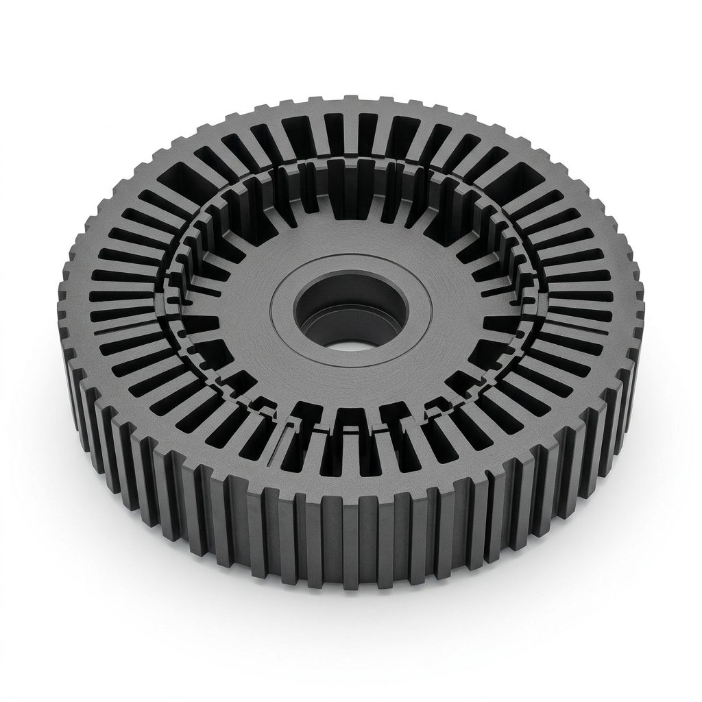
Radial flux motors have decades of industrial legacy, meaning automated winding and standard slot-liners (like Nomex paper) are highly matured. Axial Flux Permanent Magnet (AFPM) motors, however, possess geometric and manufacturing realities that make them exceptionally sensitive to 800V PD risks.
A. Flat Wire and Edge Stress
To maximize the copper fill factor and achieve extreme torque density, many high-performance AFPM stators use rectangular (flat) copper wire instead of round wire. While flat wire provides superior thermal conductivity and slot fill, the sharp corners of the rectangle create severe electric field concentrations. If the enamel coating is slightly thinner at the corners, or if the $dV/dt$ spike hits a corner void, PD inception is highly likely.
B. Coreless and Yokeless Potted Stators
Many dual-rotor AFPMs use a coreless stator (no steel teeth, just copper encased in resin) or a yokeless segmented armature (YASA) topology. In both cases, the mechanical rigidity and thermal dissipation rely entirely on the potting compound (epoxy or resin) that encapsulates the windings.
If the OEM's Vacuum Pressure Impregnation (VPI) process is imperfect, microscopic air bubbles remain trapped deep inside the resin matrix. In a 400V system, these micro-voids might survive indefinitely. In an 800V SiC system, every single trapped air bubble becomes an ignition point for partial discharge.
C. Extreme Axial Compactness
The very advantage of an axial flux motor—its "pancake" form factor—means that the phase-to-phase routing and phase-to-ground distances are inherently compressed. There is virtually no wasted end-winding space, which means high-voltage adjacent phases are packed tightly together, increasing the risk of phase-to-phase discharge if insulation coordination is not strictly calculated.
4. Engineering Comparison: 400V IGBT vs 800V SiC Impacts
For systems engineers and buyers evaluating the transition, the mechanical and electrical specifications must be updated. The table below outlines how motor constraints shift when moving an AFPM from 400V to 800V.
| Specification Parameter | 400V System (IGBT Inverter) | 800V System (SiC Inverter) | AFPM Design Impact & Mitigation |
|---|---|---|---|
| Inverter Switching Frequency | 8 - 12 kHz | 20 - 40+ kHz | Increases high-frequency AC copper losses (skin/proximity effect). Requires Litz wire or thin flat wire. |
Voltage Rise Time (dV/dt) | Less than 5 kV/μs | 10 - 20 kV/μs | Severe voltage overshoot at motor terminals. Requires inline filters or advanced insulation. |
Peak Terminal Voltage (V_peak) | ~600V | 1,200V - 1,800V | Exceeds standard enamel breakdown. Requires Grade 2 or Grade 3 PAI/PI overcoated magnet wire. |
| Primary Insulation (Wire Enamel) | Standard Polyurethane/Polyester | Corona-Resistant Polyimide (CR) | Must use CR-rated wire formulated with nano-fillers (e.g., silica) to resist PD erosion. |
| Secondary Insulation (Resin/Potting) | Standard Epoxy (Class F) | High-Tg, Void-Free Epoxy (Class N/H) | Mandatory multi-stage Vacuum Pressure Impregnation (VPI) to achieve less than 0.1% void content. |
| Testing Standard | Standard Hipot & Surge | IEC 60034-18-41 (Type I) | FAT must include offline Partial Discharge Inception Voltage (PDIV) measurement. |
5. Compliance with IEC 60034-18-41
The global standard governing insulation for low-voltage machines fed from voltage converters is IEC 60034-18-41. This document defines what a "Type I" insulation system is (an insulation system designed to be completely free of partial discharge during its operating life).
For 800V AFPMs, IEC 60034-18-41 compliance means the motor must be designed such that its Partial Discharge Inception Voltage (PDIV) is strictly higher than the maximum worst-case voltage spike generated by the SiC inverter, including the reflected wave overshoot and temperature derating factors.
If an OEM cannot provide a PDIV test report showing a safety margin above your inverter's maximum overshoot, the motor is not qualified for 800V production.
6. Sourcing & Procurement Checklist for 800V AFPMs
When engaging an AFPM manufacturer for an 800V project, procurement teams must look beyond "Holding Torque" and "Peak Power." Insulation integrity is the true measure of OEM maturity. Use the following checklist during the RFQ and supplier audit phase:
- Wire Specification Audit: Does the OEM explicitly use Corona-Resistant (CR) or Inverter-Duty magnet wire? (Request the wire supplier datasheet; look for polyimide/polyamide-imide multi-layer coatings).
- VPI Process Control: Does the OEM operate their own Vacuum Pressure Impregnation (VPI) equipment? What is their process for degassing the resin, and how do they verify the cured stator is void-free?
- PDIV Testing Capabilities: Does the OEM own high-frequency surge testing equipment capable of measuring Partial Discharge Inception Voltage (PDIV) in picocoulombs (pC)? Is this test performed on every 800V stator at End-of-Line (EOL)?
- Thermal Classification: Because SiC high frequencies generate additional Eddy currents in the stator, what is the thermal class of the entire insulation system? (Demand Class H 180°C or Class N 200°C).
- Phase Separators: Are dedicated insulating barriers (e.g., Nomex or Kapton laminates) physically placed between the U, V, and W phase crossovers in the tightly packed axial stator?
- Cable and Connector Shielding: 800V SiC switching creates massive Electromagnetic Interference (EMI). Are the high-voltage phase cables shielded, and are the glands appropriately sealed to IP6K9K standards without compromising the ground path?
If your RFQ already includes bus voltage, inverter family, cable length, cooling method, target switching frequency, and duty cycle, compare those inputs with AFPM Motor's axial flux PM motor and quality validation capabilities before supplier nomination.
7. FAQ: 800V Axial Flux Motor Specifications
Q: Can we just use a thicker layer of standard epoxy to prevent partial discharge?
A: No. Thicker epoxy does not prevent voids. In fact, if the curing profile is incorrect, a thicker mass of resin can trap more exothermic gas bubbles, actually increasing the risk of PD. The solution is high vacuum potting (VPI) and corona-resistant primary wire enamel.
Q: Will an inline sine-wave filter or $dV/dt$ choke solve the motor insulation problem?
A: Yes, placing a $dV/dt$ filter between the SiC inverter and the motor will smooth the voltage spikes and protect the motor. However, filters are heavy, expensive, and consume space—negating the size and weight benefits of choosing an axial flux motor in the first place. The optimal engineering path is to harden the motor's insulation system.
Q: Does liquid cooling help mitigate 800V insulation degradation?
A: Indirectly. Partial discharge inception voltage drops as temperature increases. By keeping the stator aggressively cooled (via direct liquid jackets or dielectric oil flooding), you maintain a higher dielectric strength in the resin and the air voids, extending the life of the motor.
Q: Can coreless AFPMs survive 800V?
A: Absolutely, provided the potting matrix is engineered correctly. Coreless stators have no steel teeth to short against, but they still face phase-to-phase and turn-to-turn PD risks. The structural resin must serve as both the mechanical chassis and a flawless dielectric barrier.
8. Navigating the 800V Transition
The shift to 800V SiC architectures represents the bleeding edge of power density, but it exposes the hidden flaws in standard motor manufacturing. For axial flux motors, where the stator is a highly integrated, tightly wound, and heavily potted assembly, mastering insulation coordination is the difference between a revolutionary powertrain and a catastrophic field failure.
Procurement and engineering teams must aggressively audit their AFPM suppliers for advanced VPI processes, corona-resistant materials, and strict adherence to IEC 60034-18-41 PDIV testing.
Sources & References
- SiC vs IGBT: EV Inverter Technology Compared. NX Technologies. Discussing the impact of steep voltage transitions and partial discharge in motor windings. Reference
- Performance and EMI Assessment of Post-800V Traction Inverter Topologies for EV Applications. IEEE EVS38 Proceedings. Analysis of high-voltage stress on motor insulation. Reference
- IEC 60034-18-41 Ed. 1.0 b:2014 - Rotating electrical machines - Part 18-41: Partial discharge free electrical insulation systems (Type I). International Electrotechnical Commission. Reference
Are you specifying an axial flux motor for a high-voltage, direct-drive application?
Validating 800V insulation requires specialized tooling and rigorous End-of-Line testing. Contact the AFPM Motor engineering team to discuss our VPI processes, Class N materials, and custom OEM manufacturing capabilities designed for next-generation SiC inverters.
Author

Categories
More Posts
PanGood's 25.73 kW/kg Axial Flux Motor Breakthrough: Implications for Robotics and eVTOL Sourcing
PanGood and NIMTE announce a record-breaking 25.73 kW/kg axial flux motor and a 300,000-unit production line. Explore the engineering and procurement impact for robotics and eVTOL.
Halbach Array Magnets in Axial Flux Motor Design: When Does It Make Sense?
Technical analysis of Halbach array magnet configurations in AFPM motors — covering flux concentration benefits, manufacturing complexity, cost tradeoffs, and practical OEM sourcing guidance.
Matching SiC Inverters to Low-Inductance Coreless Axial Flux Motors: An Engineering Guide
Engineering guide for matching SiC inverters to low-inductance coreless axial flux motors, with ripple limits, choke options, RFQ checks, and sourcing questions.