
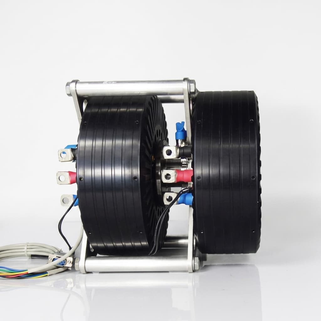
Managing Axial Magnetic Forces in AFPM Motors: Bearing Selection, Preload Drift, and L10h Life
AFPM motor bearing selection: compare axial loads, thermal preload drift and L10h fatigue life. Use the RFQ checklist to request an engineering review.
Executive Summary for Procurement & Powertrain Engineering: AFPM motor bearing selection starts with the axial force-versus-gap curve, external loads and the mechanical load path. Balanced thrust in a dual-rotor motor does not remove negative magnetic stiffness or rotor-disc bending. Compare bearing arrangements against hot and cold preload, minimum air gap and duty-cycle fatigue life before selecting a catalogue part.
Technical review: 28 October 2026. Scope: global OEM engineering and sourcing of iron-cored axial flux permanent magnet motors, including single-sided and symmetric double-sided arrangements. Coreless machines need a separate force model. Numerical examples below are illustrative calculations, not measured product performance, catalogue ratings or certification criteria. Recheck this guide by April 2027, or earlier if the bearing, inverter or duty cycle changes.
For an initial screen, use the AFPM Motor Bearing Selection Guide & Calculator, then obtain bearing-supplier approval of the actual arrangement.
1. The Core Mechanical Challenge: Axial Magnetic Attraction
When evaluating an axial flux permanent magnet motor, include axial stiffness and rotor support alongside torque density and packaging. In an iron-cored machine, magnetic attraction loads the rotor disc toward the stator even when little output torque is demanded.
A symmetric radial-flux motor ideally balances radial attraction, but eccentricity can produce unbalanced pull there too. The AFPM design challenge is the axial load path and the small available clearance between broad rotor and stator faces.
Axial magnetic forces and bearing support: conceptual diagram
Quantifying the Magnetic Pull: The Maxwell Stress Formula
For a predominantly normal air-gap field, a first screening approximation is:
Fz ≈ integral over A of [Bn(x,y)² / (2μ0)] dA
   ≈ Bg² × A / (2μ0)
μ0 ≈ 4π × 10⁻⁷ H/m
Here, A is the integrated face area in m², and Bg is a uniform normal field or the area RMS of the normal field in tesla. A peak field or a simple average field cannot generally replace that RMS value. Tangential field, slotting, leakage and saturation require a fuller Maxwell-stress/FEA evaluation; see the axial-force study in Sources.
Illustrative calculation: assume a fully active annulus with outer diameter 240 mm, inner diameter 150 mm and a uniform normal field of 0.90 T:
A = π/4 × (0.240² − 0.150²) ≈ 0.02757 m²
Fz = 0.90² × A / (2μ0) ≈ 8,885 N per active face
This is a pressure estimate, not a motor power rating or a bearing reaction. In a dual-rotor assembly, opposing face forces may close through the rotor carrier. Determine the residual thrust reaching each bearing from the actual structure and add external shaft loads.
2. Negative Magnetic Stiffness in Dual-Rotor Topologies
A dual-rotor axial flux motor can have near-zero net shaft thrust at its symmetric position. If one gap closes while the other opens, however, the force imbalance can pull the assembly farther from that position. The Soong et al. study examines this destabilizing stiffness using models, FEA and axial-force measurements.
Define Per-Face and Total Stiffness Separately
Use the local slope of the actual force-versus-gap curve, including magnet and core reluctance. For two identical faces whose gaps change equally and oppositely:
k_one = |dF/dg|                      [N/mm, one face]
Kmag ≈ 2 × k_one                     [N/mm, combined destabilizing slope]
ΔFnet ≈ Kmag × Δz                    [N, small axial displacement]
A blanket inverse-square force law is unsuitable for PM designs because magnet reluctance and saturation also affect the field. Only in the simplified gap-dominated limit F proportional to 1/g², the preceding 8,885 N example at g = 0.90 mm gives:
k_one = 2F/g ≈ 19,740 N/mm
Kmag ≈ 39,490 N/mm
At Δz = 0.05 mm, the linearized imbalance is about 1,974 N.
These figures illustrate the derivative and the two-face factor; they do not predict a particular AFPM motor. Extract slopes from force curves over the specified gap, current and temperature ranges. Rotor tilt and local disc bending require separate modes and cannot be reduced to a shaft-translation calculation.
The Mechanical Stability Condition
For this single axial mode, positive local restoring stiffness requires k_mech − Kmag > 0. Here k_mech includes bearing, shaft, carrier and housing compliance along the same load path. A project may specify an additional margin, but a universal 2.5× factor is not established by the cited sources. Verify minimum gap and dynamic response over the full duty envelope rather than treating a stiffness ratio alone as proof of reliability.
3. Bearing Topologies: Engineering Comparison
Compare exact catalogue parts, mounting geometry, lubrication and operating preload. The six arrangements below are screening options, not interchangeable capacity or speed classes. For an opposed pair, load sharing depends on thrust direction and preload; adding two single-bearing ratings does not establish pair capacity.
| Bearing architecture | Potential benefit | Main trade-off | Evidence required before selection |
|---|---|---|---|
| Back-to-back (DB) angular contact pair | Wide effective support span for moment resistance | Alignment and thermal preload need control | Pair load distribution, axial stiffness, friction and permissible speed at operating preload; relevant to drone and eVTOL propulsion studies, without implying flight qualification |
| Face-to-face (DF) angular contact pair | Alternative support geometry where mounting compliance matters | Usually less moment resistance than a comparable DB pair | Rotor tilt and minimum-gap calculation with the actual effective support span |
| Opposed tapered roller bearings | Combined radial/thrust support and potential high stiffness | Friction, lubrication and adjustment can limit operating speed | Supplier heat balance and life calculation for the duty cycle, such as AGV/AMR wheel drives |
| Deep-groove ball bearings | Compact, widely available radial support with some thrust capability | Axial clearance and stiffness may be inadequate | Catalogue thrust limit, operating clearance and full gap budget; no universal 500 W eligibility threshold for motors or AFPM generators |
| Cylindrical roller plus separate thrust bearing | Separates radial support from thrust location | Additional parts and axial space | Explicit locating/floating scheme, thrust-bearing minimum load and lubrication; choose roller subtype to avoid unintended axial overconstraint |
| Hybrid ceramic angular contact pair | Electrical insulation through ceramic rolling elements | Cost and system current paths remain relevant | Exact part ratings and inverter-system assessment; ceramic balls alone establish neither a speed uplift nor complete EDM protection |
4. Thermal Preload Drift: Rigid vs. Spring-Loaded Preload
The NSK preload guide describes position and constant-pressure methods. Both need a temperature-dependent load assessment; neither guarantees zero motion or zero preload drift.
The Coefficient of Thermal Expansion Mismatch
For an illustrative aluminium housing and steel shaft, assume constant expansion coefficients of 23.0 and 11.5 × 10⁻⁶/K respectively. Use the actual alloy properties and bearing-seat temperatures for a design calculation.
Relative axial growth = αhousing × Lhousing × ΔThousing
                      − αshaft × Lshaft × ΔTshaft
For equal 120 mm spans and equal 60 K temperature rises:
ΔL = 120 × (23.0 − 11.5) × 10⁻⁶ × 60
   = 0.0828 mm = 82.8 μm
The 82.8 μm result is relative stack growth, not a preload force or a predicted loss of clearance. Whether preload rises or falls depends on DB/DF orientation, shoulders, spacers, ring fits, radial expansion and temperature gradients. A housing temperature or the word "DB" alone does not determine the sign. Use the bearing load-deflection relationship and the complete thermal stack.
Preload Strategy Decision Matrix
| Engineering dimension | Rigid position preload | Spring preload | Locating DB pair plus non-locating support |
|---|---|---|---|
| Axial rigidity | Favors stiffness; still elastically deflects | Check spring and bearing compliance in the actual load path | Locating pair controls shaft position |
| Thermal response | Sensitive to stack growth and fits | Can reduce load variation within available spring travel | Floating support accommodates shaft growth; locating pair still needs thermal analysis |
| Air-gap control | Check bearing and structure deflection | Check displacement and contact unloading under thrust | Include local rotor bending and support tilt |
| Assembly controls | Ground spacers, shoulders and preload verification | Spring force/travel, seating and friction | Confirm free movement at the non-locating support |
| Heat and fatigue | Excess preload can increase loss and reduce life | Minimum load and spring relaxation still matter | Evaluate each support separately |
| Application boundary | Candidate where stiffness is critical | Candidate where compliance is acceptable | Candidate for traction or robotics joint drives; requires a drawing-specific review |
Use measured or simulated hot/cold preload and drag torque as acceptance evidence. Spring force changes approximately by ΔF = k_spring × Δx over a locally linear range; "constant pressure" is a design aim, not a guarantee across every temperature and speed.
5. Inverter-Induced Bearing Currents
Fast PWM edges can drive common-mode currents through the motor, bearings and connected equipment. SKF's electrical-erosion explanation describes lubricant-film discharge, micro-cratering and fluting, and why insulation must be assessed at the relevant frequency.
Review the inverter, cable, grounding and driven equipment together. Hybrid bearings, insulated rings, shaft grounding and filtering are options selected for the identified current path. A DC insulation rating alone does not establish high-frequency performance. Neither a 400 V threshold nor an 800 V SiC label makes one bearing technology universally mandatory.
For procurement, request a system drawing and test evidence for the proposed mitigation, including shaft-voltage/current measurements under representative operation. The cited SKF article explains mechanisms; it does not certify a modern SiC drive or guarantee a service interval.
6. Sourcing & RFQ Engineering Checklist
Use this checklist before requesting a bearing and air-gap engineering review. The buyer and supplier must agree mission-specific loads, margins and acceptance limits; the examples above are not standards-mandated thresholds.
- 1. Magnetic load envelope: Obtain per-face force-versus-gap curves and net thrust for current, temperature, axial offset and tilt extremes. Identify the structural path from rotor to bearings.
- 2. Stiffness and stability: State whether slopes are per-face or combined. Compare mechanical and magnetic stiffness in the same mode, with an agreed margin and dynamic-response check.
- 3. Thermal preload: Provide shaft, housing and bearing-seat temperatures, fits, shoulder/spacer dimensions, and cold/hot preload limits approved by the bearing supplier.
- 4. Fatigue rating life: Submit ISO 281 basic L10h and, where applicable, separately identified modified life. Include the part number, C, equivalent load P, speed/duty spectrum, lubrication, contamination and required reliability. Agree a target such as 20,000 h only when it fits the mission; hours do not directly convert to vehicle kilometres.
- 5. Minimum air-gap budget: Combine runout, assembly tolerances, bearing clearance/deflection, thermal growth, disc bending and support tilt without double-counting. Confirm a positive residual clearance with the project margin.
- 6. Electrical protection: Document common-mode current paths and mitigation with representative inverter, cable and grounding tests. Include any current redirected into the coupled equipment.
- 7. Drawing and assembly controls: Define TIR measurement radius, datum, shaft loads, assembly preload procedure and inspection method. Allocate runout from the gap budget rather than applying a universal percentage.
- 8. Acceptance testing: Agree speed/load/temperature points, vibration bandwidth and sensor location, drag torque, axial movement and endurance sampling. Retain results against serial numbers; a vibration screen alone does not establish fatigue life.
7. Frequently Asked Questions (FAQ)
Can a coreless stator eliminate axial magnetic thrust?
Removing stator iron reduces the rotor-to-stator iron-attraction component, but does not remove rotor-to-rotor attraction, current-dependent forces or external thrust. A yokeless stator may still contain iron teeth and must not be assumed coreless. Request the actual magnetic circuit and force curves before changing bearing capacity.
Why can DB bearings resist rotor tilting better than DF bearings?
For comparable bearings and spacing, DB contact-line geometry provides a wider effective support span. Moment stiffness also depends on bearing size, operating preload and housing compliance. The label DB does not establish a permissible rotor tilt or eliminate disc bending.
How do we calculate L10h when axial load dominates?
Use the bearing supplier's equivalent-load rule for the exact part and arrangement. Where applicable, P = X × Fr + Y × Fa, with X, Y and the transition factor e taken from that catalogue. Opposed bearings also require internal load distribution and preload to be considered.
The ISO 281 basic rating-life method can be expressed as:
L10h = [10⁶ / (60 × n)] × (C/P)^p
p = 3 for ball bearings; p = 10/3 for roller bearings
n = constant speed in rpm; C and P use the same force unit
Reproducible screening example: if the selected ball bearing has C = 30 kN, the supplier-derived P = 3 kN and n = 3,000 rpm, L10h ≈ 5,556 h. Raising P by 25% to 3.75 kN reduces the estimate to 2,844 h, about 51% of the original. These assumed ratings and loads do not select a real bearing.
L10 denotes a basic fatigue life associated with 90% survival under the method's assumptions; it is not a guaranteed maintenance interval. Modified life introduces reliability and lubrication/contamination factors. For variable duty, use the applicable load-speed spectrum method. Static overload, grease life, electrical erosion and thermal damage need separate checks.
Is wave-spring preload suitable for traction motors?
It can be suitable if the resulting shaft motion, minimum bearing load and residual gap pass the duty envelope. A locating angular-contact pair with a separate non-locating support is another option. Do not add a spring to a cylindrical roller support without defining whether axial freedom occurs inside the bearing or at a ring fit.
What is the maximum allowable axial runout?
There is no universal runout limit for every AFPM rotor. Allocate TIR within the full minimum-gap budget, specify the measurement radius and distinguish static face TIR from hot running deflection. For example, a buyer may allocate 0.020 mm TIR, but that value needs validation for the particular gap and structure.
How does liquid cooling affect bearing preload?
Cooling may keep the housing below shaft temperature and change the thermal stack. Measure or model the bearing seats and rings as well as the coolant. Preload can rise or fall depending on the mounting arrangement; confirm the result with the supplier's thermal/preload model and hot/cold tests.
8. Sourcing & Engineering Summary
Select bearings from a coupled electromagnetic, structural and thermal model. The useful sourcing deliverable is a traceable load envelope, gap budget, preload window and fatigue calculation for an identified arrangement. Resolve missing inputs before comparing headline life hours or bearing material upgrades.
Sources & References
Public references checked on 28 October 2026. Catalogue values and full standards must be applied to the actual design; the calculations in this article do not claim compliance or first-party test results.
- Soong, W. L., Roshandel, E., Cao, Z., Mahmoudi, A., & Kahourzade, S. (2025). Axial Force Negative Stiffness in Axial-Flux Electric Machines. IET Electric Power Applications, 19, e70095; DOI 10.1049/elp2.70095. University repository record for the study of force/gap dependence, double-sided machines and tilt; does not prescribe a universal stiffness safety factor.
- International Organization for Standardization. ISO 281:2007 — Rolling bearings: Dynamic load ratings and rating life. Official scope and publication record for basic and modified rating life; not a guarantee against every bearing failure mode.
- NSK Global. Bearing ABCs: 8 — Preload. Manufacturer guidance on opposed pairs, rigidity, preload loss, and position versus spring preload; actual selection needs the part-specific catalogue.
- SKF Evolution. Prevention of electric erosion in bearings (15 September 2001). Manufacturer explanation of current paths, lubricant-film discharge and frequency-dependent insulation. Foundational mechanism reference, not a present-day SiC qualification specification.
Need Engineering Review for Your AFPM Motor Bearing Program?
For a supplier comparison or prototype review:
- Use the AFPM Motor Bearing Selection Tool for an initial screen with its stated assumptions.
- Review the available AFPM Quality Validation and Rotor & Magnet Assembly services.
- Contact the AFPM Motor engineering team with your force-versus-gap data, bearing arrangement, duty cycle, temperatures, inverter details and packaging limits to discuss the remaining validation work.
Author

Categories
More Posts
Mercedes-Benz Launches Series Production of Axial Flux Motors: Supply Chain & Procurement Impact
Mercedes-Benz begins large-scale series production of axial flux motors in Berlin. Explore the supply chain implications, technology scaling, and strategic impact for procurement and engineers.
Axial Flux vs. Radial Flux Motors: A Detailed Engineering Comparison
An engineering analysis of the technical differences, torque density advantages, magnetic flux paths, and manufacturing tradeoffs between axial flux and radial flux permanent magnet motors.

Specifying Axial Flux Motors for 800V Architectures: Insulation & PD Risks
Learn how to specify 800V axial flux motors for SiC inverters: PDIV limits, VPI checks, insulation classes, and RFQ evidence to request from suppliers.