Engineering screening • Reviewed 2026-10-23 • Magatom Dynamics Co., Ltd.

AFPM Motor Bearing Selection: Calculator & Guide

Compare magnetic pull, fatigue life and rotor tilt with an illustrative bearing model. Use the guide below to prepare a supplier review.

Interactive toolIllustrative • live results

Bearing screening calculator

Illustrative assumptions, not supplier approval. All fields are required; loads are non-negative magnitudes.Read assumptions and limits.

View current results ↓
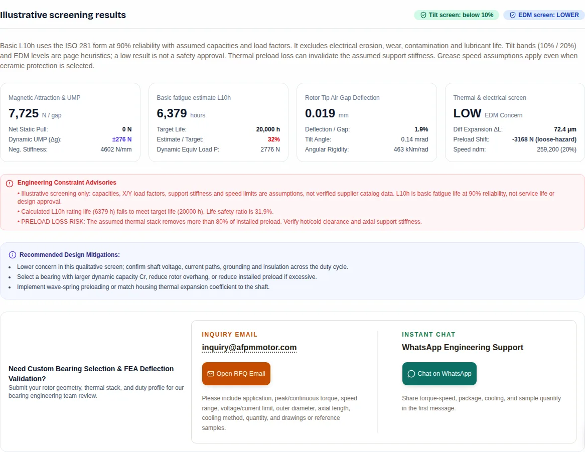
Screen updated: basic fatigue estimate 6379 hours; support-tilt movement 0.019 mm; EDM concern low. These are illustrative estimates, not design approval.
Input ranges and units
  • Outer diameter: 50–1000 (units shown on the field label).
  • Inner diameter: 20–999 (units shown on the field label).
  • Nominal air gap: 0.3–10 (units shown on the field label).
  • Magnet thickness: 1–30 (units shown on the field label).
  • Peak gap flux: 0.2–1.6 (units shown on the field label).
  • Pole embrace: 0.5–0.95 (units shown on the field label).
  • Gap offset tolerance: 0–9.99 (units shown on the field label).
  • Operating speed: 0–40000 (units shown on the field label).
  • Target life: 500–200000 (units shown on the field label).
  • External axial load magnitude: 0–100000 (units shown on the field label).
  • External radial load magnitude: 0–100000 (units shown on the field label).
  • External tilt moment magnitude: 0–10000 (units shown on the field label).
  • Rotor mass: 0–1000 (units shown on the field label).
  • Ambient temperature: -60–200 (units shown on the field label).
  • Operating temperature: -60–200 (units shown on the field label).
  • Bearing span: 15–500 (units shown on the field label).
  • Rotor overhang: 5–300 (units shown on the field label).
  • Installed preload: 0–20000 (units shown on the field label).
  • Inverter DC voltage: 0–1500 (units shown on the field label).

Inner diameter must be below outer diameter. Gap offset must be below nominal gap. Zero and sub-1 rpm duty need a supplier static/low-speed review.

Edit geometry, loads and bearing assumptions
1. Topology & Electromagnetic Stresses
Axial magnetic pull and negative stiffness parameters
2. Duty Cycle & Applied Mechanical Loads
External thrust, radial drive, and dynamic tilting moments
3. Bearing Selection & Inverter Environment
Arrangement, preloading, span, and electrical isolation

Illustrative screening results

Tilt screen: below 10%EDM screen: LOWER

Basic L10h uses the ISO 281 form at 90% reliability with assumed capacities and load factors. It excludes electrical erosion, wear, contamination and lubricant life. Tilt bands (10% / 20%) and EDM levels are page heuristics; a low result is not a safety approval. Thermal preload loss can invalidate the assumed support stiffness. Grease speed assumptions apply even when ceramic protection is selected.

Magnetic Attraction & UMP
7,725 N / gap
Net Static Pull:0 N
Dynamic UMP (Δg):±276 N
Neg. Stiffness:4602 N/mm
Basic fatigue estimate L10h
6,379 hours
Target Life:20,000 h
Estimate / Target:32%
Dynamic Equiv Load P:2776 N
Rotor Tip Air Gap Deflection
0.019 mm
Deflection / Gap:1.9%
Tilt Angle:0.14 mrad
Angular Rigidity:463 kNm/rad
Thermal & electrical screen
LOW EDM Concern
Diff Expansion ΔL:72.4 μm
Preload Shift:-3168 N (loose-hazard)
Speed ndm:259,200 (20%)
Recommended Design Mitigations:
  • Lower concern in this qualitative screen; confirm shaft voltage, current paths, grounding and insulation across the duty cycle.
  • Select a bearing with larger dynamic capacity Cr, reduce rotor overhang, or reduce installed preload if excessive.
  • Implement wave-spring preloading or match housing thermal expansion coefficient to the shaft.
Need Custom Bearing Selection & FEA Deflection Validation?
Submit your rotor geometry, thermal stack, and duty profile for our bearing engineering team review.

Inquiry Email

[email protected]

Please include application, peak/continuous torque, speed range, voltage/current limit, outer diameter, axial length, cooling method, quantity, and drawings or reference samples.

Instant Chat

WhatsApp Engineering Support

Share torque-speed, package, cooling, and sample quantity in the first message.

1. What the screen can help you decide

Selection conclusions and their evidence
DecisionWhy it mattersEvidence / limit
Start with the support load pathBalanced motor thrust does not remove individual rotor-disc forces or external shaft loads.AFPM electromagnetic context [1]; the rigid-rotor model here is a simplification.
Compare DB, DF and integrated ringsMoment span, misalignment tolerance and packaging compete. No arrangement is mandatory for every AFPM motor.Layout sketches below are illustrative; obtain supplier contact stiffness.
Check fatigue and static duty separatelyL10h does not cover shock indentation, EDM, wear or grease life.ISO 281 [2] and ISO 76 [3].
Validate thermal and electrical behaviorPreload may change with temperature; insulation must match the complete current path.SKF system guidance [5]; no immunity or service-life guarantee.

References [1]–[6] are linked in the source register. Every numerical example on this page is illustrative unless a source is explicitly named.

2. Magnetic pull and topology boundaries

The screen assumes uniform normal flux over the pole-covered annulus: A = π(Dₒ² − Dᵢ²)/4, p = αₚB²/(2μ₀), F = pA, with diameters converted to metres. For 260/160 mm, 0.85 T and αₚ = 0.75, p ≈ 215.6 kPa = 21.56 N/cm² and F ≈ 7,112 N per gap. This uses peak B as a uniform field approximation; a spatial field integral is needed for a real machine. [1]

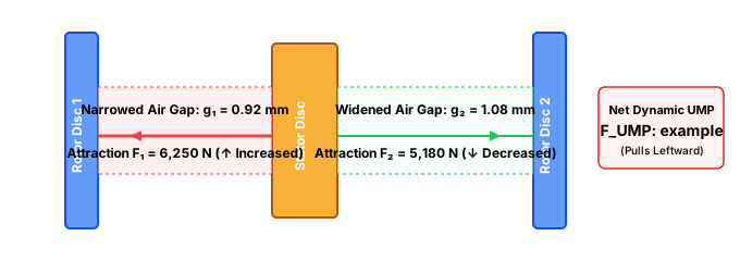
Illustrative Figure 2: Dual-Rotor Unbalanced Magnetic Pull (UMP) Under Tolerance Offset Δg

Unbalanced Magnetic Pull in Axial Flux Dual Rotor Machine
Illustrative asymmetric gaps create a net force. Use the current scenario results for modeled UMP; geometry and flux determine its magnitude.
Topology treatment in this screen; not a universal machine model
TopologyAssumptionMissing physics / next check
Single rotor / single statorOne-sided normal attraction enters the support load.Check assembly, axial housing deflection and static capacity.
Dual rotor / iron statorNominal net thrust cancels; offset produces a linear UMP estimate.Each disc still carries normal force; tie structure and force transfer require FEA.
Dual stator / internal rotorNominally balanced; gap asymmetry produces a restoring-force deficit.Verify local flux and bearing load distribution.
Coreless dual rotorReduced (15% of yokeless) UMP sensitivity is a teaching assumption.Rotor-to-rotor attraction and structural disc bending remain; obtain electromagnetic results.

3. Reproduce the calculations and understand the limits

The table below describes the implemented screening model. Bearing examples are synthetic teaching data; no manufacturer rating, matched-pair certification, speed approval or fit recommendation is implied.

Model equations, assumptions and exclusions
OutputImplemented methodDecision boundary
Axial pull / UMPg_eff = g + l_m/1.05; K_mag = qF/g_eff; UMP = K_mag Δg. q = 2 (single-sided), 4 (yokeless/internal rotor), 4.4 (slotted), 0.6 (coreless).Linearized sensitivity; no saturation, leakage, spatial field or rotor disc bending.
Support reactionsRadial magnitudes add to rotor weight. M = M_ext + Fr·overhang; front reaction = Fr + M/span. Axial load adds external thrust, UMP, net pull and installed preload.Conservative magnitude screen, no signed load sharing or pair internal contact solution.
Equivalent load PP = XFr + YFa. ACBB: (1,0.92) below Fa/Fr = 0.68, otherwise (0.67,1.41). Tapered: (1,1.5) below 0.4, otherwise (0.67,2.2). Cross roller: (1,0.7). DGBB: (1,0) below 0.28, otherwise (0.56,1.63).All X/Y and threshold factors are assumptions. Replace with exact supplier factors and pair-rated C/P.
Basic L10h10⁶/(60n) × (C/P)^p; p = 3 for balls, 10/3 for rollers. No artificial life cap.ISO 281 form [2], 90% reliability. No zero-speed hours, modified life or system reliability claim.
Tilt stiffnessk_a = C0[kN] × 1.5 × (0.8 + 0.6·preload/500) N/μm; Kθ = k_a·10⁶·L_eff²/2. DB/DF: L_eff = L ± D_bearing·tan(α). Cross roller: C0[kN] × 65,000 Nm/rad.Uncalibrated stiffness assumptions. Thermal loss, housing/shaft/disc bending and spring compliance are not coupled into Kθ.
Tip movementKnet = Kθ − Kmag·1000·r_avg²; θ = M/Knet; δ_tip = Rθ. Stop if Knet ≤ 0 or θ ≥ 0.1 rad.10%/20% gap bands are page heuristics, not standard acceptance limits. Total runout and axial translation are excluded.
Thermal driftΔL = (α_housing−α_shaft)LΔT. Steel/Al: 11.5/23; Ti/Al: 8.6/23 × 10⁻⁶/K. DF ΔF = k_aΔL; DB uses −0.7k_aΔL. Compliant example uses 30 N/mm.Equal uniform temperatures and a simplified stack. Actual ring temperatures, fits, spring stroke and stiffness must be measured.
EDM concernHeuristic score from DC bus, switch type, ndm and mitigation. Lower/moderate/high/critical are triage categories.No measured capacitance, shaft voltage, pulse rate or failure probability. A lower score is not a safety approval.

The application runs synchronously in your browser; edits immediately update the screen. Invalid or missing fields withhold results. A boundary message provides a static-check or structural-review path when the model cannot produce a meaningful result.

4. Compare support arrangements

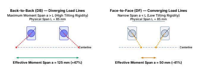
Illustrative Figure 1: Angular Contact Ball Bearing Paired Arrangements & Tilting Moment Centers

Back-to-Back vs Face-to-Face Bearing Contact Line Spread
DB widens the moment span in this illustrative layout. Compare supplier stiffness, misalignment tolerance and the actual support geometry before choosing DB or DF.
Family tradeoffs; shortlist by duty rather than motor power alone
CandidatePotential benefitCost / mismatch risk
DB angular-contact pairLarger effective moment span than DF for comparable geometry.Matched pairs, precision shoulders and preload calibration add cost.
DF angular-contact pairCan accommodate mounting misalignment better than DB.Smaller moment span may increase tip movement; validate the thermal stack.
Tapered-roller pairUseful for combined thrust and radial duty.Friction, lubrication, minimum load and thermal setting may dominate at speed.
Cross-roller ringCompact integrated support for combined loads and moments.Ring mounting and bolt distortion matter; obtain a moment-load and speed rating.
Deep-groove + springSimple support when axial duty and required stiffness allow.Check clearance, thrust rating and loss of stiffness; no universal power cutoff.
Hybrid rolling elementsElectrical isolation across rolling contacts and lower centrifugal mass.Higher purchase cost; does not resolve every drive-system current path. See SKF [5].

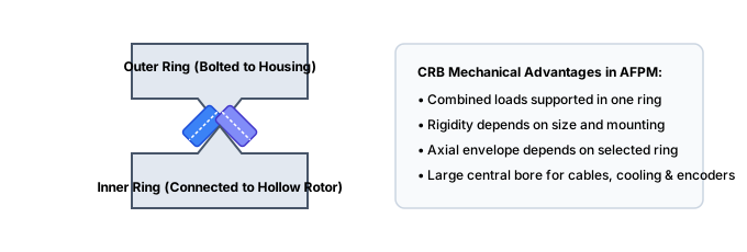
Illustrative Figure 4: Cross-Roller Bearing 90° V-Groove Internal Geometry & Moment Capacity

Cross-Roller Bearing Geometry
Alternating 90° cylindrical rollers provide line contact in all directions, supporting combined radial, axial and moment loads when correctly mounted.

5. Inspect the illustrative bearing data

Synthetic model inputs — not orderable specifications. C/C0 are assumed assembly values.
ExampleBore / OD / width (mm)C / C0 (kN)Assumed grease ceiling (rpm)
Illustrative 40 mm DB angular-contact pair40 / 68 / 1532.5 / 2418000
Illustrative 50 mm DB angular-contact pair50 / 80 / 1641.5 / 33.515000
Illustrative 60 mm DF angular-contact pair60 / 95 / 1854 / 4513000
Illustrative 40 mm hybrid DB pair40 / 68 / 1534 / 24.524000
Illustrative 40 mm tapered-roller pair40 / 80 / 19.7576.5 / 835600
Illustrative 50 mm cross-roller ring50 / 80 / 1321.2 / 28.83200
Illustrative 40 mm spring-loaded deep-groove bearing40 / 68 / 1517.8 / 11.69000

Width describes the illustrative bearing element, not the full paired support envelope. Pair load sharing, induced thrust and mounting stiffness are unresolved. Obtain a supplier calculation with the exact designation, suffix, lubrication, fits and operating temperatures before ordering.

6. Build an air-gap budget, then validate it

The calculator estimates support tilt only. A small number can coexist with unacceptable axial shaft motion, rotor-disc bending, magnet height variation or preload loss. Add those terms with tolerances and measured hot/cold runout to form a minimum-gap budget. Do not interpret the green band as a rotor-clearance approval.

A practical air-gap validation budget
ContributionHow to obtain itIf unknown
Support tilt under peak momentSupplier contact model plus shaft/housing FEA.Use the screen to compare layouts only.
Disc and housing bendingCoupled magnetic-pressure and structural model.Reserve clearance; do not release tooling from L10h alone.
Assembly runout and axial locationMeasure rotor perimeter and end-play on assembled units.Set a drawing-specific inspection plan.
Hot/cold and transient changesDuty-cycle thermal test including seals and thrust.Mark minimum operating gap unverified.
Request a review with your current screening inputs ↑

7. Balance preload, thermal growth and friction

For the illustrative aluminium/steel stack, 100 mm span and 60 K rise give ΔL = (23−11.5) × 10⁻⁶ × 100 × 60 = 0.069 mm. An assumed 30 N/mm spring changes force by 2.07 N over that travel. This is an arithmetic example, not a guarantee of constant preload: spring travel, relaxation, thermal gradients and support stiffness remain to be checked.

Rigid setting can improve stiffness but magnifies dimensional errors. A compliant setting can absorb growth while reducing axial restraint. Heating and cooling are both modeled; the sign for a real assembly depends on locating shoulders, ring temperatures and the DB/DF stack. Request preload-versus-temperature and drag-torque measurements rather than transferring the simplified sign rule directly to production.

8. Evaluate bearing currents as a drive-system problem

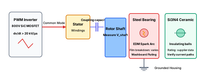
Illustrative Figure 3: Inverter dv/dt Capacitive Coupling & Bearing Current Fluting Mechanism

Bearing Currents and EDM Fluting in Inverter-Driven Motors
Si3N4 hybrid ceramic balls break the electrical discharge circuit, reducing the rolling-contact current path; verify the complete drive.

PWM common-mode excitation can couple into the rotor and discharge through lubricant films. Insulation, grounding and shielded cabling address different paths. SKF explains why the complete motor, inverter, cables and load must be considered together. The fixed voltages in the schematic are illustrative; they are not measured AFPM thresholds. [5]

Electrical mitigation choices, without a universal immunity claim
OptionWhat it addressesWhat to verify
Hybrid ceramic bearingHigh impedance through rolling-element contacts.Seal/shield paths, both bearing locations and connected equipment.
Grounding ring / brushProvides a bypass path for shaft current.High-frequency impedance, contact condition and contamination.
Insulated bearing ringInterrupts a current path with a coating.Coating integrity and frequency-dependent capacitance.
Cable/shield/filter changesCan reduce excitation or improve return paths.Measurements on the installed drive; avoid displacing current into the load.

9. Keep fatigue, grease life and speed separate

Basic L10h excludes electrical erosion, wear and corrosion. Lubricant selection needs operating viscosity, contamination, bearing temperature, load and ndm = n(d+D)/2. Use the supplier viscosity chart and lubrication-life method; this page does not calculate κ, grease life or a relubrication interval. [2]

The calculator always compares speed to its assumed grease ceiling. Selecting ceramic electrical protection does not select oil lubrication or authorize higher speed. Oil feed, seals, churning loss and cooling must be designed and verified as a system.

10. Know what commercial examples cannot tell you

Public model names do not establish an internal bearing bill of materials. No verified teardown or OEM bearing drawing is available in this page’s evidence set for EMRAX 228, YASA 750/P400, Magnax AXF275, Saietta AFT140 or Koenigsegg Quark. Their contact angles, preload packs and electrical protection are therefore unknown / pending OEM confirmation. The calculator scenarios are independent teaching examples, not reconstructions of these motors.

For sourcing, request bearing designations and matched-set ratings, permitted shaft loads, continuous/peak duty, preload procedure, grease specification and electrical mitigation evidence. Compare warranty and maintenance conditions as well as quoted component cost.

11. Five worked screening scenarios

Choose the matching scenario in the calculator to edit all inputs. These are hypothetical duties, not field results.

AFPM motor bearing selection calculator showing the EV traction scenario, fatigue estimate, tilt movement and preload warning
Actual software execution captured 2026-10-23: EV traction scenario, 260/160 mm annulus, 1 mm gap, 0.88 T, 4,800 rpm, 300/650 N external axial/radial loads and 25 Nm moment. The assumed model returns about 6,379 h against a 20,000 h target, 0.019 mm support-tilt movement and a preload-loss warning. Reproduce it with the first calculator scenario. This is software evidence, not measured motor performance or customer validation.

260 mm EV Traction Pod (750V SiC)

Dual-rotor yokeless topology with high torque density and regenerative braking

Illustrative DB hybrid layout: compare tilt, fatigue screening and thermal preload loss; verify inverter current paths on the complete drive.

Premise: 260/160 mm active annulus; gap 1.0 mm; 4800 rpm; axial/radial loads 300/650 N; moment 25 Nm.

Process: geometry → magnetic sensitivity → assumed bearing reactions → fatigue and tilt.

Output: L10h ≈ 6,379 h vs 20000 h target; support-tilt movement 0.019 mm; thermal state loose-hazard; EDM screen low.

Next: Lower concern in this qualitative screen; confirm shaft voltage, current paths, grounding and insulation across the duty cycle. Confirm stiffness at operating preload and validate the complete gap budget.
Compare this scenario in the tool ↑

160 mm eVTOL Direct-Drive Propeller

Air-core dual-rotor drone motor under continuous axial aerodynamic thrust

Coreless dual-rotor architecture eliminates stator iron magnetic pull. Constant wave-spring preloading absorbs thermal shifts during high-altitude climb cycles.

Premise: 160/100 mm active annulus; gap 1.2 mm; 3200 rpm; axial/radial loads 420/90 N; moment 12 Nm.

Process: geometry → magnetic sensitivity → assumed bearing reactions → fatigue and tilt.

Output: L10h ≈ 79,718 h vs 5000 h target; support-tilt movement 0.006 mm; thermal state stable; EDM screen moderate.

Next: Review bearing-current paths and measure shaft voltage. Evaluate grounding, shielding and insulation with the drive supplier. Confirm stiffness at operating preload and validate the complete gap budget.

Compare this scenario in the tool ↑

320 mm Hollow-Shaft Robot Joint

High-torque direct-drive collaborative robot actuator with high moment loads

Integrated cross-roller bearing delivers massive tilting moment rigidity in a thin 13 mm axial envelope, resisting heavy robot arm dynamic cantilever forces.

Premise: 320/220 mm active annulus; gap 0.9 mm; 450 rpm; axial/radial loads 1200/1800 N; moment 180 Nm.

Process: geometry → magnetic sensitivity → assumed bearing reactions → fatigue and tilt.

Output: L10h ≈ 766 h vs 30000 h target; support-tilt movement 0.022 mm; thermal state stable; EDM screen low.

Next: Lower concern in this qualitative screen; confirm shaft voltage, current paths, grounding and insulation across the duty cycle. Confirm stiffness at operating preload and validate the complete gap budget.

Compare this scenario in the tool ↑

360 mm Marine Pod Propulsor

Submerged high-thrust single-stator dual-rotor propulsion motor

Illustrative tapered-roller pair under 3.8 kN thrust; check the calculated life against the target and validate seals, lubrication and thermal preload.

Premise: 360/240 mm active annulus; gap 1.4 mm; 950 rpm; axial/radial loads 3800/1200 N; moment 45 Nm.

Process: geometry → magnetic sensitivity → assumed bearing reactions → fatigue and tilt.

Output: L10h ≈ 4,087 h vs 40000 h target; support-tilt movement 0.010 mm; thermal state loose-hazard; EDM screen low.

Next: Lower concern in this qualitative screen; confirm shaft voltage, current paths, grounding and insulation across the duty cycle. Confirm stiffness at operating preload and validate the complete gap budget.

Compare this scenario in the tool ↑

140 mm Compact AGV Wheel Hub

Low-cost, compact pancake wheel drive for automated guided logistics vehicles

Illustrative single-sided motor: magnetic thrust remains on the support; compare the modeled load with a supplier static and fatigue calculation.

Premise: 140/80 mm active annulus; gap 0.8 mm; 1200 rpm; axial/radial loads 150/850 N; moment 20 Nm.

Process: geometry → magnetic sensitivity → assumed bearing reactions → fatigue and tilt.

Output: L10h ≈ 3,924 h vs 15000 h target; support-tilt movement 0.017 mm; thermal state stable; EDM screen low.

Next: Lower concern in this qualitative screen; confirm shaft voltage, current paths, grounding and insulation across the duty cycle. Confirm stiffness at operating preload and validate the complete gap budget.

Compare this scenario in the tool ↑

12. Define release checks before ordering

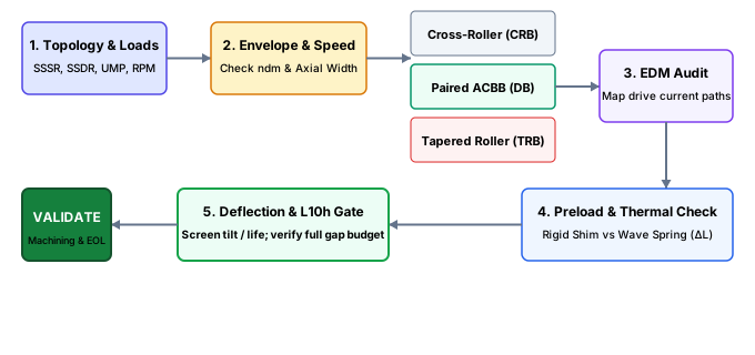
Illustrative Figure 5: Complete AFPM Bearing Selection & Preload Engineering Decision Tree

AFPM Bearing Selection Roadmap
Systematic engineering qualification workflow from electromagnetic boundary conditions to precision EOL preload sign-off.

The diagram is a planning workflow. Passing its illustrative tilt and fatigue checks does not authorize release. Agree drawing-specific fits, geometric tolerances and acceptance limits with the bearing supplier. ISO 21940-11 covers rigid-rotor balancing procedures; a universal G1.0 requirement cannot be inferred from an AFPM rotor speed alone. [6]

  1. Calculate steady, peak and stationary loads, minimum loads and supplier static safety factors under ISO 76. [3]
  2. Resolve internal contact distribution, clearance and misalignment using a supplier method. ISO 16281:2025 replaces the withdrawn 2008 technical specification; its modified-life method has specific hybrid-bearing limitations. [4]
  3. Measure drag torque and axial compliance at defined loads and temperatures; calibrate acceptance limits on qualified units.
  4. Measure assembled hot/cold air gaps, runout and vibration under the intended duty. A generic vibration or megohmmeter limit is insufficient to prove bearing health or high-frequency electrical protection.
  5. Confirm current paths, lubrication, seals, balance, manufacturing capability and maintenance terms before design sign-off.

13. Sources and evidence boundaries

Public source records checked 2026-10-23; full standards are not reproduced and this page does not claim compliance.

Published ; reviewed . Review these methods and sources every six months, next due 2027-04-23, or earlier when a cited standard or supplier method changes.

[2] ISO 281:2007 — Dynamic load ratings and rating life

Published 2007; confirmed 2021; revision in development

Basic rating life at 90% reliability; modified-life influences include lubrication and contamination.

Limit: Wear, corrosion and electrical erosion are outside scope. Assumed model inputs do not establish compliance.

[3] ISO 76:2006 — Static load ratings

Published 2006; Amendment 1:2017; revision in development

Static ratings, equivalent static load and guidance on static safety factors.

Limit: This calculator does not compute a supplier-specific P0 or static safety factor.

[4] ISO 16281:2025 — Modified reference rating life

Published January 2025; corrected August 2025; replaces ISO/TS 16281:2008

Internal load distribution, operating clearance, misalignment and tilt in fatigue calculations.

Limit: Its modified reference life calculation is not applicable to hybrid bearings; the screen does not implement this method.

[5] SKF — Prevention of electric erosion in bearings

SKF Evolution technical article, 2001; mechanism reference, checked 2026-10-23

PWM bearing-current mechanisms, system return paths and frequency-dependent insulated-bearing behavior.

Limit: Historical examples are not present-day AFPM failure thresholds. Motor, inverter, cables and load need system validation.

14. Bearing selection questions

Loads and fatigue

Why does an AFPM bearing layout need a magnetic-force check?

Axial magnetic pressure can load rotor discs and locating supports. The bearing reactions depend on the complete rotor/stator load path, not only motor torque. The force and stiffness model here is illustrative; validate it with electromagnetic and structural data.

Do dual rotors remove every axial load?

Nominal shaft thrust may cancel in a symmetric assembly. Local rotor-disc forces, gap asymmetry and external thrust remain. Check both structural forces and support reactions.

What does L10h mean?

It is basic rolling-contact fatigue life at 90% reliability under the ISO 281 framework. It is not guaranteed service life, grease life or a prediction of EDM, wear or corrosion.

Can I calculate hours at zero speed?

No. The hours conversion divides by running speed. For stationary or oscillating duty, obtain supplier static-load, indentation and lubrication checks; the tool withholds L10h at zero rpm.

Is a low tip-deflection percentage a safe air gap?

No. The screen covers support tilt only. Include axial translation, disc bending, assembly runout, temperature and dynamic loads in a complete gap budget. The 10% and 20% bands are page heuristics.

Architecture and preload

Must every AFPM motor use back-to-back bearings?

No. DB can offer a larger effective moment span than DF for comparable geometry. Selection also depends on misalignment, thrust direction, packaging, lubrication and supplier stiffness data.

When should I consider a cross-roller ring?

Consider it when compact combined radial, axial and moment support is useful. Verify speed, moment rating, mounting flatness, bolting and deformation with the supplier rather than applying a universal rpm cutoff.

Can a deep-groove bearing be used?

Possibly, if its axial load capability, internal clearance, minimum load and assembly stiffness meet the duty. Motor power alone is insufficient to accept or reject it.

What is the tradeoff between a rigid setting and a spring?

A rigid setting can increase restraint but is sensitive to dimensional and thermal stack errors. A spring can absorb growth, with its own stroke, fatigue, relaxation and stiffness limits.

Does aluminium always reduce preload in DB?

No universal sign rule applies. Relative ring temperatures, locating shoulders, shaft and housing expansion and fits determine the result. The screen assumes uniform temperatures and a simplified DB/DF stack.

Electrical and lubrication checks

Do ceramic rolling elements guarantee a failure-free motor?

No. Hybrid elements provide high electrical impedance across rolling contacts, but the full current path, seals, shields, connected load and grounding still need evaluation. Mechanical fatigue, contamination and lubrication failures remain possible.

Is a grounding ring always enough?

It depends on the current path and high-frequency impedance. Check installed shaft voltage, contact condition, contamination, bonding and the driven equipment with the inverter and motor suppliers.

Does choosing ceramic protection authorize oil speeds?

No. The screen retains its assumed grease speed ceiling. Lubrication method and allowable speed require a separately verified bearing and assembly specification.

Can I use basic L10h as the relubrication interval?

No. Determine lubricant viscosity, temperature capability, contamination, fill quantity, seal performance and maintenance intervals with the lubricant and bearing suppliers.

Manufacturing and sourcing

Are the calculator bearings verified catalog products?

No. They are illustrative families with assumed capacities, stiffness, load factors and speed limits. Obtain an exact designation and matched-set calculation before ordering.

Can I copy a commercial motor’s bearing arrangement from this guide?

No verified OEM bearing drawing or teardown is available in this page’s evidence set. Internal bearing designs and preload mechanisms for the named commercial motors are unknown pending OEM confirmation.

Which machining fits and balance grade should I specify?

Choose from the bearing supplier’s fit guidance and the actual rotating load, bore size, temperature and speed. Set geometric tolerances from the assembled air-gap budget. ISO 21940-11 is the rigid-rotor balancing framework, not a universal G1.0 rule.

What should I send for a bearing review?

Provide rotor geometry, magnetic-force results, air-gap budget, shaft/support drawings, steady and peak loads, speed and duty spectrum, temperatures, inverter/cable details, target reliability and maintenance constraints.

15. Prepare a supplier review

Send rotor geometry, magnetic force/FEA data, air-gap budget, shaft drawing, peak and continuous loads, duty spectrum, temperatures, inverter/cable details, target reliability and maintenance requirements. Treat all calculator numbers as preliminary assumptions until the supplier confirms ratings and the assembly passes validation.

Inquiry Email

[email protected]

Please include application, peak/continuous torque, speed range, voltage/current limit, outer diameter, axial length, cooling method, quantity, and drawings or reference samples.

Instant Chat

WhatsApp Engineering Support

Share torque-speed, package, cooling, and sample quantity in the first message.