
100kW motor sizing
100kW Axial Flux Motor Calculator
Estimate required torque, speed and DC current. Then compare duty and cooling evidence for EV, marine and aviation requirements.
Reviewed
Calculate operating pointDecision summary
100kW Integration Realities
A 100kW rating requires careful integration planning around bus voltage, DC bus current, phase current limits, and thermal management.
Compare ratings on the same duty basis
A 100kW label alone does not establish run time. Request continuous output, peak duration, cooldown and the full load cycle before shortlisting a motor.
Cooling needs operating-point evidence
Do not prescribe oil cooling from power alone. Validate the proposed coolant, inlet temperature, flow, ambient conditions and winding temperatures at your sustained load.
Use DC current for the DC supply budget
At 100kW shaft output and 94% assumed DC-to-shaft efficiency: 354.6 A at 300 V, 266.0 A at 400 V and 133.0 A at 800 V. Phase RMS current needs separate winding and inverter data.
Compare installed systems, not headline mass
Ask for motor, inverter, cooling loop, gearbox and mounting mass separately, with a common continuous duty target and package drawing.
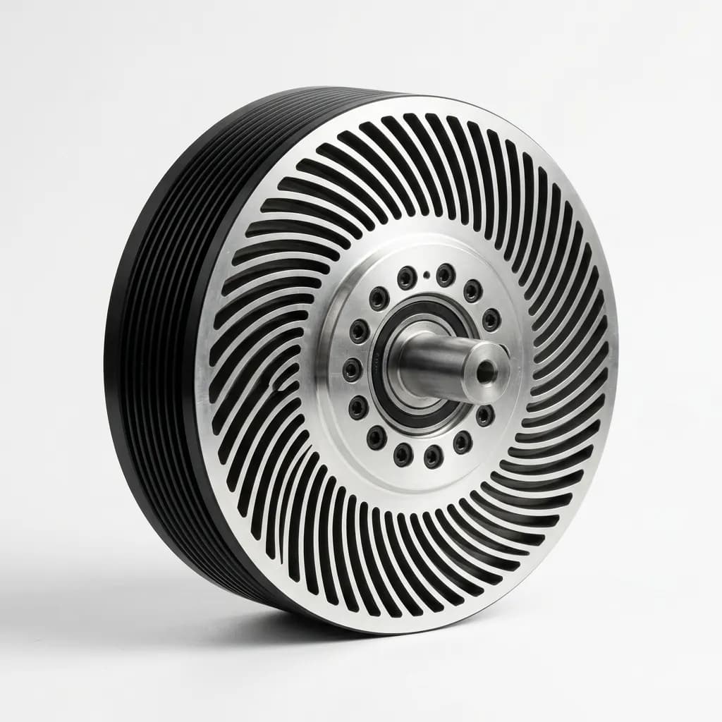
System boundary
Continuous and Time-Limited Duty
The difference between a 100kW peak motor and a 100kW continuous motor depends on the verified duty cycle, coolant conditions, and thermal dissipation path.
Calculated at 100kW shaft output and 94% combined DC-to-shaft efficiency; auxiliaries excluded. Values share the calculator model.
| Architecture | Estimated DC Bus Current | Cable / DC-Link Impact | Integration Note |
|---|---|---|---|
| 300 V DC | 354.6 A | Review DC current and thermal margins | Confirm pack sag, inverter limits and insulation for this winding |
| 400 V DC | 266.0 A | Review DC current and thermal margins | Confirm pack sag, inverter limits and insulation for this winding |
| 600 V DC | 177.3 A | Lower DC current; verify voltage compatibility | Confirm pack sag, inverter limits and insulation for this winding |
| 800 V DC | 133.0 A | Lower DC current; verify voltage compatibility | Confirm pack sag, inverter limits and insulation for this winding |
Method and uncertainty
100kW motor torque, DC current and cooling estimates
By AFPM Motor. Published , reviewed . This is an engineering screening method, not a hardware test report.
Reproduce the calculation
Mechanical power: P = T × 2π × RPM / 60. With P in kW, torque T = 9549.2966 × P / RPM; RPM = 9549.2966 × P / T.
DC current = 100,000 / (Vdc × η). Here η = 0.94, the assumed combined inverter and motor efficiency. At 400 V this gives 266.0 A; 90–97% efficiency would give 277.8–257.7 A before auxiliaries.
The same assumption implies 6.4kW total inverter-plus-motor loss. This does not locate the heat or size a cooling loop; losses vary across the operating map.
Known, assumed and still unknown
Known: the required 100kW shaft power and your voltage/speed or torque inputs. Application presets are illustrative requirements.
Assumed: 94% efficiency. Input windows (300–800 V, 500–15,000 RPM or 50–2,000 Nm) and review triggers (250 A, 8,000 RPM, 300 Nm) organize screening; they are not a motor capability envelope.
Unknown: available torque, voltage compatibility, duration, phase current, thermal limits, installed mass, price and delivery. Request supplier maps and qualification data before selecting hardware.
S1 describes sustained load to thermal equilibrium; S2 needs a run time and subsequent cooling; S3 needs the repeating load/rest cycle and duty factor. A marketing peak rating does not automatically establish S2 or S3 duty. Read the duty definitions and confirm the applicable rating standard with the supplier. IEC scope and limits.
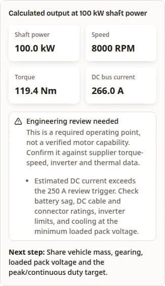
Reproduce this software example
Captured September 23, 2026 from this calculator: Passenger EV Traction, 400 V, 8,000 RPM, 100 kW shaft output and 94% assumed efficiency. Choose that preset to reproduce 119.4 Nm and 266.0 A DC.
The image records software execution. It is not a motor test, customer case study or endorsement. The result panel alone is shown.
Reproduce the 100kW calculationPublished evidence
Read the rating boundary before comparing
Manufacturer listings reviewed September 23, 2026. These examples have different duty and package boundaries; neither is a verified match for every calculator result.
| Model and source | Published rating | Package | Conditions and decision limit |
|---|---|---|---|
| Turntide AF400S | 106kW continuous; 338kW for 20s; 5,000 RPM maximum | 40kg dry; 115 × 381.7mm (L × D) | Indirect water/ethylene-glycol cooling; 45°C ambient, 55°C inlet, 8 L/min. Winding, voltage and switching frequency affect the map. Does not validate the 8,000 RPM EV preset. |
| Evolito D250 | 180kW peak; 10,000 RPM maximum. Continuous: N/A in listed metrics. | 14.5kg; 370 × 125mm (D × L) | Peak duration and thermal test boundary: N/A in listed metrics. Earlier announcement differs; obtain a revision-specific datasheet before deriving power density or continuous capability. |
Selection tradeoffs
Choose a system to validate
Use these procurement questions to compare alternatives at the same duty and shaft output. Price and installed mass remain unknown until quoted.
| Approach | When to investigate | Tradeoff to quantify | Minimum next step |
|---|---|---|---|
| Axial flux direct drive | Short axial space and a matching low-speed torque map | Outside diameter, phase current, shaft loads and sustained heat | Overlay the actual load curve on continuous and peak maps |
| Motor plus gearbox | Required shaft torque exceeds a suitable motor’s direct-drive map | Gearbox mass, efficiency, noise, lubrication and service | Compare installed envelope and duty-adjusted losses |
| Matched radial flux drive | Package flexibility or an existing qualified motor/inverter pairing | System mass, cooling, prototype cost and delivery versus an axial option | Request comparable itemized quotes and load-point tests |
Evidence and method
Application Benchmarks & Risks
Separate published manufacturer examples from calculated requirements before finalizing your powertrain.
RFQ Evidence Checklist
| Spec Area | Ask For | Decision Value |
|---|---|---|
| Rating basis | Continuous kW, peak kW and duration, S2 run time or S3 duty factor where applicable, rest period, and ambient temperature | Separates true 100kW continuous packages from short-burst traction ratings. |
| Cooling circuit | Coolant type, flow rate, pressure drop, max winding temperature, and sensor placement | Shows whether 100kW can be sustained without thermal derating. |
| Electrical interface | DC link range, inverter phase RMS/peak current, connector type, and cable size | Prevents DC bus current from being confused with motor phase current. |
| Torque-speed map | Peak and continuous torque curves, base speed, efficiency map, and field-weakening limit | Confirms whether your operating point stays inside the efficient envelope. |
| Mechanical package | Motor mass, outside diameter, axial length, shaft loads, bearing rating, and IP rating | Validates packaging, power density, and axial-load risk together. |
Worked Screening Examples
Illustrative requirements, not deployment results. Each row assumes 100kW shaft output and 94% DC-to-shaft efficiency, then applies the formulas above. Reproduce it with the matching Application Example in the calculator.
| Application | DC Voltage | Speed | Torque | DC Current | RFQ Note |
|---|---|---|---|---|---|
| Passenger EV Traction | 400 V | 8000 RPM | 119.4 Nm | 266.0 A | Share vehicle mass, gearing, loaded pack voltage and the peak/continuous duty target. |
| Marine Propulsion | 350 V | 3000 RPM | 318.3 Nm | 304.0 A | Provide the propeller curve, cruise duration, shaft loads and available coolant conditions. |
| Aviation / e-VTOL | 600 V | 2500 RPM | 382.0 Nm | 177.3 A | Provide thrust, hover/climb/cruise duty, redundancy and qualification requirements. This estimate does not establish flight suitability. |
| Performance Motorcycle | 300 V | 6000 RPM | 159.2 Nm | 354.6 A | Share acceleration targets, battery limits, sustained load and the diameter/length envelope. |
Common Integration Risks
Risk: Overheating or premature derating
Trigger: Treating a peak rating as continuous, or using test data taken with colder coolant than your installation.
Mitigation: Request a steady-state thermal test at your worst coolant/ambient conditions and temperature-based derating. Flow rate alone cannot establish cooling capacity.
Risk: Undersized electrical interface
Trigger: Using nominal pack voltage or treating calculated DC current as phase RMS current.
Mitigation: At 300V the estimate is 354.6A DC; at 800V it is 133.0A DC. Check DC and phase circuits separately against pack sag, current ratings and winding/inverter data.
Risk: Speed or shaft-load mismatch
Trigger: Assuming a required torque-speed point is inside a motor’s capability, especially for direct-drive propellers.
Mitigation: Obtain rotor speed, bearing load and back-EMF limits. Compare a gearbox or a different winding if the direct-drive point is outside the verified map.
Risk: Installed cost exceeds the budget
Trigger: Comparing bare motor prices while excluding inverter development, cooling, tooling, qualification and service spares.
Mitigation: Request itemized prototype and production quotes. Compare a matched radial-flux drive where axial length and mass constraints are relaxed; no price advantage is assumed here.
Frequently Asked Questions
Sizing and duty
What torque does a 100kW motor need?
At 3,000 RPM, 100kW at the shaft requires 318.3 Nm; at 8,000 RPM it requires 119.4 Nm. These are required operating points, not proof that a particular motor can deliver them.
Can it run at 100kW continuously?
Only with a supplier continuous rating and thermal evidence covering your load and cooling conditions. Neither a peak label nor this calculator establishes continuous capability.
How big or heavy is a 100kW motor?
Power alone cannot specify dimensions or mass. Use a configuration-specific drawing and installed mass budget; the manufacturer benchmarks below are examples, not a universal range.
Does every 100kW motor need direct oil cooling?
No. Cooling architecture is design-specific. The benchmark includes an indirect-liquid-cooled model. Ask for temperatures and losses at the required operating point before selecting the cooling loop.
Electrical integration
What voltage is required?
This tool screens 300–800 V DC. Voltage selection needs winding back-EMF, speed, inverter and insulation data. Raising voltage reduces estimated DC current for fixed output and efficiency; it does not prove that a winding supports that voltage.
Is DC bus current the motor phase current?
No. The DC estimate budgets power at the supply. Phase RMS/peak current depends on the winding, torque constant, power factor and inverter control; obtain these limits separately.
Does an axial flux motor require a SiC inverter?
Topology alone cannot prescribe semiconductor type or switching frequency. Match inductance, electrical frequency, current ripple, voltage/current limits and cooling with the inverter supplier.
Is 94% a measured efficiency?
No. It is an illustrative combined DC-bus-to-shaft assumption, including inverter and motor losses but excluding auxiliaries. Replace it with measured efficiency and add auxiliary demand for final sizing.
Using the result and buying a system
What do the boundary messages mean?
They are editorial review triggers, not universal motor ratings. Every valid result still needs torque-speed, electrical and thermal evidence. Multiple warnings can apply to one point.
What if my target is outside the input range?
Do not force the nearest value to stand in for your requirement. Use the RFQ for a custom review, including the actual operating point and duty cycle; restore an example to continue exploring.
Can I use the aviation example for flight approval?
No. It calculates shaft demand only. Propeller matching, redundancy, qualification and mission duty remain separate engineering requirements.
When should I compare a radial flux alternative?
When axial length is less constrained or an existing matched drive can meet the duty. Compare installed cost, efficiency at the same load points, mass, cooling, service and delivery terms. A topology label does not establish the better system.
Sources & References
IEC 60034-1:2026 — rating and performance (Published March 13, 2026; reviewed September 23, 2026)
Key Finding: Rating framework reference. The listing excludes rail and road vehicle machines, which it refers to IEC 60349; application-specific requirements must be checked.
Evidence boundary: Official scope listing only; the full paid standard was not reviewed and this page does not establish compliance.
Read IEC scope and editionTurntide — AF400S manufacturer specifications (Reviewed September 23, 2026; page publication date not stated)
Key Finding: The benchmark below uses the AF400S entry and its stated coolant/ambient boundary, not an IWM or complete drive-unit rating.
Evidence boundary: Manufacturer-published values; not an independent test or a guarantee at the calculator’s speed and voltage.
Read AF400S specificationsEvolito — D250 product page (Reviewed September 23, 2026; page publication date not stated)
Key Finding: Current page lists 180kW peak and 14.5kg. Its figures differ from the 240kW / 13kg in a February 2025 announcement; confirm the revision and configuration before comparing.
Evidence boundary: Manufacturer listing; continuous rating and full thermal conditions are not provided in the listed performance metrics.
Read current D250 metricsEvolito — Flying Whales announcement (Published February 4, 2025; reviewed September 23, 2026)
Key Finding: Historical configuration context for the D250 discrepancy; do not mix the announcement’s peak power with the current page’s mass.
Evidence boundary: Primary announcement, not a current procurement datasheet.
Read the dated announcementCME — motor duty definitions (Reviewed September 23, 2026; publication date not stated)
Key Finding: Explains sustained S1 operation, S2 run and cooling periods, and repeating S3 load/rest cycles.
Evidence boundary: Manufacturer terminology guide, not a 100kW performance test or certification assessment.
Read the duty definitionsAFPM Motor — 100kW screening method (Updated September 23, 2026)
Key Finding: Uses mechanical power balance and an assumed 94% combined inverter-plus-motor efficiency. No thermal, electromagnetic or vehicle simulation is performed.
Evidence boundary: Reproducible arithmetic; hardware feasibility remains unverified.
Review formulas and limitsRFQ closeout
Turn the 100kW Screening Result into an RFQ
Send the target voltage, torque-speed point, duty cycle, cooling boundary, shaft load, package envelope, and validation target so AFPM Motor can review feasibility against a real manufacturing path.
Send 100kW RFQ Data