
Review the complete axial load path
A per-face magnetic estimate can identify a load worth investigating. It cannot establish restraint, press capacity, or guide stiffness.
Basis and limitsAssembly planning ·
Estimate one-face magnetic pull.
A per-face magnetic estimate can identify a load worth investigating. It cannot establish restraint, press capacity, or guide stiffness.
Basis and limitsSeparate TIR, flatness, bearing movement, thermal growth, and structural deflection. A cold nominal gap alone cannot prove clearance.
Basis and limitsAdhesive chemistry and joint geometry matter. Supplier typical data support candidate selection; they do not release a rotor.
Basis and limitsDefine balancing and insulation qualification for the actual design, then specify calibrated production checks and traceable results.
Basis and limitsFor a uniform field normal to an active face, use magnetic pressure B²/(2μ₀) times the effective area. This is an approximation supported by MIT course notes and Parviainen’s equation 4.1. The reluctance model below is a declared screening assumption; it does not reconstruct the complete motor circuit.
A = π(OD² − ID²)/4; Aeff = 0.76 × A.
Bg = Br × lm / (lm + 1.05 × g).
F(g) = Bg² × Aeff / (2μ₀), where μ₀ ≈ 4π × 10⁻⁷ H/m.
|dF/dg| = 2 × 1.05 × F / (lm + 1.05 × g), in N/mm when lm and g are in mm.
| Quantity | Reproducible model value | Meaning / unresolved input |
|---|---|---|
| Active annulus / effective magnet area | 329.87 / 250.70 cm² | 76% coverage is an assumption, not a drawing measurement. |
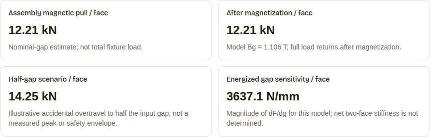
| Energized field / force per face | 1.106 T / 12.21 kN | Room-temperature idealized magnetic circuit. |
| Half-gap scenario | 14.25 kN at 0.5 mm | An overtravel sensitivity example, not a maximum assembly load. |
| One-face gap sensitivity | 3637.1 N/mm | Derivative magnitude; not net rotor stiffness or a fixture stiffness requirement. |
| Press / guides / bearing preload | Undetermined | Needs circuit, approach travel, force path, stiffness, fits, and design load cases. |
Br assumptions: N38SH 1.22 T; N42SH 1.30 T; N45UH 1.35 T; N52H 1.44 T. Confirm the actual supplier B-H curve and temperature. Leakage, saturation, pole geometry, armature current, fringing, flexure, and multi-gap coupling are excluded. No confidence interval or conservative bound is established. Coreless, Halbach, ferrite, saturated, and operating-current cases require a separate model.
| Layout | Main load question | Closure evidence required |
|---|---|---|
| SSSR: one stator / one rotor | Where does the one-sided magnetic force react? | Bearing, housing, rotor, and restraint load paths in assembly and operation. |
| SSDR: one stator / two rotors | How is the second rotor restrained as the magnetic circuit closes? | Both discs, inter-rotor attraction, common hub, and fixture reaction versus travel. |
| DSSR: two stators / one rotor | How does axial offset upset nominal force cancellation? | Both gap forces, net force versus offset, bearing support, and disc deflection. |
Parviainen discusses cancellation and manufacturing misalignment for a dual-stator prototype; cancellation at a centered operating point does not remove each face’s load. Tool topology selections change these review questions, while the displayed force remains a one-face approximation. Study and scope.
Use this sequence to organize a drawing-specific work instruction. Each hold point needs an approved setting and evidence; the page does not provide an executable universal SOP.
Approved retention drawing and traceable adhesive/cure records; no universal cure schedule or speed cutoff is inferred.
Drawing-defined flatness and insulation acceptance; no generic grinding or oven recipe.
Released bearing arrangement, datum scheme, clearance/preload, and runout limits.
Approved minimum clearance and reaction path throughout the stroke; one-face force is not press capacity.
Record approved limits, calibrated equipment, test conditions, and unit-level results; this tool does not certify release.
For a defined datum and load condition, allocate the nominal clearance to assembly offsets, surface errors, bearing motion, thermal movement, disc deflection, and measurement uncertainty. Evaluate worst combinations in the approved stack; the entries below are review inputs, not a validated tolerance sum.
| Contribution | Known / example / unknown | How to close the gap |
|---|---|---|
| Nominal gap | 1.000 mm — entered design target | Verify at specified radius, angle, temperature, and load. |
| Rotor-face TIR | 0.080 mm — editorial allocation (8%) | TIR is max minus min over 360°, without ±. Datum and stack mapping require design review. |
| Stator flatness | 0.050 mm — editorial allocation (5%) | Independent surface allocation; actual acceptance comes from the drawing. |
| Bearing motion / preload | Unknown | Obtain supplier limits and the actual bearing arrangement. |
| Thermal movement / magnetic deflection | Unknown | Use the specified cold/hot load envelope and structural model or measurements. |
| Gauge uncertainty / assembly offsets | Unknown | Qualify measurement capability and assembly datum repeatability. |
| Minimum running clearance | Undetermined | Cannot be released while stack contributions and their directions remain unknown. |
The tool scales only the two labeled example allocations: TIR = min(0.100 mm, 8% of gap) and flatness = min(0.060 mm, 5% of gap). Neither is an industry standard. Do not subtract them from nominal gap and infer a safe running clearance.
| Candidate / method | Verified scope | Qualification still required |
|---|---|---|
| 3M DP490 | Two-component epoxy; condition-specific typical data in the July 2024 TDS. | Magnet coating, substrate, surface preparation, cure, bondline, fatigue, fluids, and temperature. |
| LOCTITE 648 | Anaerobic urethane methacrylate retaining compound for cylindrical fitting parts; May 2021 TDS. | Supplier confirmation for actual joint geometry. Do not substitute it into a generic two-part epoxy procedure. |
| Mechanical containment | Design-specific retention option; no universal RPM cutoff established here. | Load, thermal growth, fatigue, balance, electrical losses, manufacturing tolerances, and controlled validation. |
Read the 3M and Henkel source limits. A product’s typical coupon strength is not the allowable stress of a rotor bond. For retention review, calculate the magnet load from mass, radius, and speed, then validate the actual joint and containment at the agreed conditions.
| Gate | Purpose | Information needed before acceptance |
|---|---|---|
| Geometry and free rotation | Confirm assembled datums and clearance. | Drawing limits, measurement radius, bearing preload, cold/hot conditions, and minimum clearance. |
| Rotor balancing | Control residual unbalance for service operation. | Rigid/flexible behaviour, speed range, agreed grade/limits, correction planes, and repeatability. |
| Insulation qualification | Establish suitability of the winding system. | Type I/other system, terminal waveform, converter stress, applicable standard edition, and qualification method. |
| Routine electrical checks | Detect assembly defects on each unit. | Approved resistance, insulation, dielectric/surge methods and settings, calibrated equipment, and traceable results. |
| Back-EMF, vibration, and spin | Confirm the agreed functional baseline. | Speed, temperature, phase measurement method, containment, and design-specific acceptance limits. |
ISO 21940-11 addresses rotors with rigid behaviour. The BSI catalogue for EN 60034-18-41 identifies Type I insulation qualification and quality-control scope. Public catalogue summaries do not establish this motor’s production test settings.
| Stage / route | Benefit sought | Cost or mismatch risk | Minimum next action |
|---|---|---|---|
| Prototype | Expose load paths and rework issues early. | A prototype success may hide variation and operator dependence. | Record each build, actual loads, dimensions, and rework steps. |
| Pilot | Establish repeatability and inspection capability. | Premature automation can lock in an unstable datum or cure process. | Run controlled trials and measure process and gauge capability. |
| Series | Maintain traceability and monitored closure. | Automation economics depend on takt, uptime, yield, and changeover. | Approve the control plan, recovery logic, and capability evidence before line purchase. |
| Post-assembly magnetization | Reduce magnetic handling load before magnetization. | Magnetizer access, field penetration, and verified pole pattern may not be feasible. | Ask the magnetizer supplier to review the complete assembled magnetic circuit. |
Illustrative calculations using the same model as the tool, not customer case studies, measured outcomes, or validated motor performance. Use the corresponding EV, UAV, or Servo preset to reproduce them.
SSDR · OD/ID 260/160 mm · gap 1.0 mm · magnet 6.0 mm · N42SH · pre-magnetized.
12.21 kN / face
Decision: Review second-rotor restraint and the rotor-to-rotor circuit before requesting a fixture concept.
Release evidence remains pending; no actual deflection, yield, or vibration improvement is claimed.
Reproduce in the toolSSSR · OD/ID 160/90 mm · gap 0.8 mm · magnet 4 mm · N52H · pre-magnetized.
5.89 kN / face
Decision: Check the sustained axial reaction and lightweight housing deflection before committing to the bearing arrangement.
Release evidence remains pending; no actual deflection, yield, or vibration improvement is claimed.
Reproduce in the toolDSSR · OD/ID 320/190 mm · gap 1.2 mm · magnet 7 mm · N45UH · pre-magnetized.
20.61 kN / face
Decision: Model force imbalance against rotor offset, then define monitored closure and gap inspection hold points.
Release evidence remains pending; no actual deflection, yield, or vibration improvement is claimed.
Reproduce in the toolA one-face result used as a press rating can omit reaction loads, stiffness, overtravel, and stored energy.
Next: Review the complete load-versus-travel and recovery case with the fixture designer.
A detailed fixture or line quotation before datum and cure validation can create rework and inspection costs.
Next: Start with a measured pilot and explicit unknowns; agree capability targets before automation.
Coreless, Halbach, ferrite, flexible rotors, operating-current, or multi-gap circuits are outside this estimate’s verified scope.
Next: Use a geometry-specific magnetic/structural model and the corresponding validation plan.
If the form cannot produce a result, load a reference preset or send the available drawing with missing dimensions marked pending. Mechanical insertion force, material temperature capability, production yield, cycle time, and cost remain undetermined by this page.
Published by Magatom Dynamics Co., Ltd.. Published: . Last updated: .
Sources checked October 21, 2026. Document dates are shown separately from this review date. Supplier revisions and applicable standard editions must be confirmed for procurement; catalogue scope is not full-text conformity evidence.
2005; printed pp. 74 and 87, equation 4.1
One-face attraction approximation, axial-load cancellation with centered geometry, and assembly load concerns. The thesis gives 7.3 kN per stator for one modeled prototype at a 1.5 mm gap.
Limit: A specific machine study, not a universal force range, tooling capacity, or production tolerance.
2011 notes, hosted in the Spring 2009 course; §6.3.2, equations 6.3.29–30
Magnetic pressure and the area-times-pressure force approximation in an idealized air gap.
Limit: Supports the pressure relation. The Br values, coverage, and single-gap reluctance approximation used here are declared screening assumptions.
2016 edition; official catalogue checked 2026-10-21
Procedures and unbalance tolerances for rotors that behave rigidly.
Limit: The public scope does not choose an AFPM balance grade, correction-plane count, or speed limit. Review the applicable edition and rotor behaviour with the designer.
July 2024 revision, English-Canada
DP490 is a two-component epoxy; the sheet provides condition-specific handling, cure, and strength data.
Limit: 3M identifies these as typical data. They do not qualify a magnet coating, bondline, operating temperature, or rotor retention design.
May 2021 revision
An anaerobically curing urethane methacrylate retaining compound intended for cylindrical fitting parts.
Limit: It is not a two-part epoxy. A cylindrical-fit application does not establish suitability for an exposed flat magnet-to-disc joint.
Catalogue scope checked 2026-10-21
Qualification and quality-control tests for Type I, partial-discharge-free insulation systems in converter-fed rotating machines.
Limit: This scope is not a universal production Hi-Pot or PDIV setting. Obtain the applicable standard and agree test conditions for the actual winding and drive.
It estimates uniform-field attraction on one active face from dimensions and an illustrative magnet Br, compares a half-gap scenario, and builds a topology and production review checklist. It does not size a press or release a manufacturing process.
A multi-gap machine needs its complete magnetic circuit and reaction path modeled. This tool keeps the same one-face approximation and changes the review plan; it does not invent topology-specific force multipliers.
Zero is only the ideal magnetic contribution before magnetization. Mechanical fits, friction, residual magnetism, and handling loads remain unknown. The tool separately shows the magnetic load after magnetization.
No. It is an explicit overtravel scenario at half the entered gap, not a measured peak or a worst-case bound. Fixture capacity needs validated load-versus-travel data, restraint, stiffness, and the complete reaction path.
Specify the datum, measurement radius, rotation, thermal and load condition, and minimum clearance. Total indicated runout is the maximum minus minimum reading over a revolution; it is a nonnegative span, not a ± value.
No. The 5% flatness and 8% runout allocations are editorial examples with caps, not sourced tolerances. Bearing movement, thermal growth, disc deflection, assembly offsets, and measurement uncertainty must also fit the released clearance budget.
No. 3M identifies DP490 as a two-component epoxy; Henkel identifies 648 as an anaerobic retaining compound for cylindrical fitting parts. Qualify the actual joint, coating, cure, and environment with the supplier.
This page establishes no universal RPM cutoff. Magnet mass and radius, speed, temperature, bond strength, fatigue, and the containment design determine the retention load case. Release requires design-specific analysis and controlled validation.
Ask the designer to specify rotor behaviour, service speed, permissible residual unbalance, and correction planes. ISO 21940-11 covers rigid-behaviour rotors; diameter alone cannot select G1.0 or G2.5.
Agree the insulation system, rated voltage, inverter terminal stress, test method, voltage, duration, and acceptance criteria. Type I insulation qualification and routine production tests have different purposes. This tool supplies no universal electrical test voltage.
The volume selection changes the review plan from unit-level measurement to pilot capability or series monitoring and traceability. It does not change the physics or prove that a particular automation level is economical.
Send available drawings, topology, magnet condition, expected speed, thermal envelope, bearing arrangement, volume, and known constraints. Mark missing fields pending and ask for a load-case and control-plan review before requesting tooling.
Include drawings, topology, magnetic circuit, magnet condition, operating speed and thermal envelope, bearing arrangement, expected volume, and unresolved constraints. The tool’s contact action includes your current inputs and labels its estimates as provisional.
Inquiry Email
Please include application, peak/continuous torque, speed range, voltage/current limit, outer diameter, axial length, cooling method, quantity, and drawings or reference samples.
Instant Chat
+86 188 5797 1991
Share torque-speed, package, cooling, and sample quantity in the first message.