Interactive calculator ·

AFPM Motor Back EMF

Estimate back EMF, Ke, Kt and inverter headroom. Edit the example below.

Back EMF & Inverter Headroom

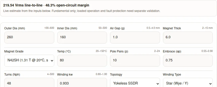
219.54 Vrms line-to-line · 48.3% open-circuit margin

Default example from the inputs below. Fundamental only; loaded operation and fault protection need separate validation.

All numeric inputs are required. Dimensions and magnet thickness are in mm; gap is per face; turns are total series turns in one terminal phase path. The equivalent circuit assumes an iron return path and uniform radial field. Coreless/PCB stators and parallel branch imbalance need separate modeling.

Line-to-Line EMF

219.54 Vrms

Phase: 126.75 Vrms

EMF Constant Ke

73.18 Vrms/krpm

Phase peak: 0.5706 V·s/rad

Torque Constant Kt

1.21 Nm/A line RMS

0.856 Nm/A line peak

DC Link Headroom

48.3%

No-load: 5797 RPM

Open-Circuit Screen: Open-circuit EMF is below the ideal inverter ceiling. Loaded voltage margin is unverified: check current, resistance, inductance and bus sag.

Yokeless SSDR: one stator between two rotors. The equivalent circuit assumes symmetric gaps and magnets; segmented iron teeth are not an air-core winding. Ke in V·s/rad uses phase peak voltage and mechanical speed. Kt uses terminal line current at unity displacement factor, with no reluctance torque or losses. The no-load ceiling speed excludes impedance drops, dead time and DC bus sag. Harmonic winding factors and measured THD are unknown.

Check loaded voltage requirements and next steps

Fundamental Coil EMF (120° Displacement)

fe = 500 Hz | 1 Cycle (360° elec)
0°90°180°270°360°+179.26V0V-179.26V
Phase A Phase B Phase C
Fundamental only; THD unknown

Magnetic Field & Thermal Sensitivities

Air gap flux density (Bg):1.032 T
Operating Br (80°C):1.216 T
Thermal derating from 20°C:-7.2%
Air gap sensitivity (per 0.1 mm):±1.51%

Inverter Matching & Harmonics

Max linear inverter output:424.26 Vrms
No-load ceiling speed:5797 RPM
Pole-field ratios (5th / 7th):8.28% / 14.29%
Fundamental LL peak:310.48 Vpk

Inquiry Email

[email protected]

Please include application, peak/continuous torque, speed range, voltage/current limit, outer diameter, axial length, cooling method, quantity, and drawings or reference samples.

Instant Chat

+86 188 5797 1991

Share torque-speed, package, cooling, and sample quantity in the first message.

Four Decisions Before Selecting an AFPM Winding

Match a loaded voltage budget

The ideal SVPWM ceiling is Vdc/√2 line RMS. A positive open-circuit margin is only an initial screen; include impedance, current and minimum bus voltage.

Method and evidence

Check gate-off behavior at maximum speed

Fundamental peak above Vdc flags possible diode conduction. Fault current, energy absorption and measured harmonic peaks remain unknown.

Method and evidence

Separate reversible temperature drift from damage

With the assumed −0.12%/°C coefficient, 20→120°C reduces EMF by 12%. This is reversible behavior, not a demagnetization qualification.

Method and evidence

Use the local gap derivative

The default gap/magnet circuit gives approximately 1.51% per 0.1 mm, not a universal 10–15%. Tilt and asymmetric gaps need additional analysis.

Method and evidence

Published · Last updated · Publisher: Magatom Dynamics Co., Ltd.. Review due April 2027, or earlier if model assumptions or supplier data change.

Use this page to compare preliminary winding inputs and prepare a review. Its uniform-field, iron-return-path model does not establish a certified operating envelope, continuous torque or a production acceptance limit.

AFPM motor back EMF calculator showing the default EV winding inputs and fundamental voltage estimate
Calculator execution captured on 2026-10-21 using the EV traction preset; expand its complete inputs in the worked examples to reproduce it. This is software output, not a measured motor test or customer result. No customer endorsements are claimed.

A Reproducible Fundamental EMF Calculation

The equations below define this tool’s equivalent circuit. It assumes a rectangular pole field, constant radial flux density, balanced sinusoidal currents and total series turns N along one terminal phase path. Annulus integration includes the radial velocity effect under that constant-field assumption. See Parviainen, equation 2.28 for axial-machine fundamental EMF context.

A = π(Do² − Di²)/4; A_pole = A/(2p); f = pn/60

Br(T) = Br20[1 + (αBr/100)(T − 20)]; Bg = Br(T)lm/(lm + μr kc g)

B1,peak = (4/π)Bg sin(αpπ/2)

Φ1 = (2/π)B1,peak A_pole = (8/π²)Bg A_pole sin(αpπ/2)

E_phase,peak = 2πf kw N Φ1; E_phase,RMS = E_phase,peak/√2

Star: E_LL,RMS = √3 E_phase,RMS. Delta: E_LL,RMS = E_phase,RMS.

ke = E_phase,peak/ω_mechanical. Kt_phase,RMS = 3ke/√2; Kt_phase,peak = 1.5ke.

Kt_line = Kt_phase in Star; Kt_line = Kt_phase/√3 in balanced Delta. Ke_LL = 1000 E_LL,RMS/n in Vrms/krpm.

Flux uses geometry in metres; lm and g may both be in mm in the reluctance ratio. μr=1.05 and kc=1.02 (1.08 for the slotted option) are screening assumptions. The flux integral supplies the 2/π factor; multiplying peak B1 by pole area alone would overstate EMF by π/2. Torque follows power balance 3E_phase,RMS I_phase,RMS = Tω at unity displacement factor.

What the Equivalent Circuit Knows and What It Cannot Resolve

Model boundaries and the next validation step
EffectIncluded hereUnknown / next step
Radial conductor velocityAnnulus area integration for constant radial BgRadially varying Bg and magnet shape require radial slices or 3D FEA.
Slot openingsFixed assumed Carter factorDerive permeance and harmonic effects from actual slot/tooth geometry.
Leakage and iron saturationOmittedUse material B-H curves and geometry-specific FEA; no universal correction percentage is asserted.
Rotor topologyEquivalent symmetric magnetic path and total series turnsDisc count alone does not multiply EMF. Model asymmetric gaps and parallel branches separately.
Loaded motor and fault behaviorFundamental no-load voltage onlyObtain Rs, Ld/Lq, currents, bus range and circuit dynamics.

Analytical, FEA and measured comparisons in the cited thesis demonstrate why leakage and geometry matter. Their error does not define a ± accuracy band for this tool. Calibrate Ke at known temperature and speed before committing winding tooling.

Inverter Matching: No-Load Ceiling Versus Loaded Base Speed

Ideal fundamental line-to-line modulation limits
ModePeak / VdcRMS / VdcUse in this tool
Sinusoidal PWM√3/2 ≈ 0.8660√3/(2√2) ≈ 0.6124Supported linear limit
SVPWM1.00001/√2 ≈ 0.7071Supported linear limit; +15.47% versus SPWM
Six-step2√3/π ≈ 1.1027 (fundamental)√6/π ≈ 0.7797 (fundamental)Comparison only; beyond linear modulation, harmonic/current analysis required

Reported headroom = 100(1 − E_LL,RMS/V_limit). Reported no-load ceiling speed = 1000V_limit/Ke_LL. Neither includes winding drops or bus sag. The 12% review trigger is an internal screening assumption, not an ISO, IEC or SAE requirement.

d-axis (Re)q-axis (Im)V_inv,max = Vdc / √2 (SVPWM)E_BackEMFIs · Rsj·ωe·Ls·IsTerminal Voltage (Vs)Loaded voltage allowance (project-specific)

Diagrams scroll horizontally for detail on small screens. The phasor is qualitative. For a steady-state loaded check use vd = Rs id − ωe Lq iq and vq = Rs iq + ωe(Ld id + ψPM), with a consistent phase-peak convention and current limits. See TI’s dq equations. Compare √(vd²+vq²) to available phase-peak voltage at minimum Vdc. Choose project headroom from this check.

Next action: if margin is low, review turns, speed and current demand together. Fewer turns or Delta increases voltage room while requiring more terminal current for a given torque; neither proves a cheaper inverter or a thermally feasible design.

Gate-Off Generation and Protection Trade-Offs

DC LinkCapacitor+ Vdc BusInverter 6-Diode Bridge (Gates Tripped OFF)D1D2D3D4D5D6I_regenAFPM MotorSpinning @ Top RPME_pk > V_dc(Freewheeling Surge)Hazard: Extreme Overvoltage & Destructive Regenerative Braking Torque

When gate pulses stop, permanent-magnet flux remains. A line-to-line peak above the instantaneous DC bus plus diode drops can drive current through the bridge. The tool compares the fundamental peak to the entered Vdc; it omits diode drops, actual harmonic peaks, inductance, battery acceptance and transient energy. It flags a review condition rather than predicting bus rise or braking torque.

Fault-response options to validate with the drive supplier
StrategyIntended effectRisk / verification
All gates offDiodes can return generated energy to DC linkCheck maximum speed, battery/DC sink acceptance, bus capacitance and disconnection sequence.
Active short circuit (high or low side)Intended circulating current path reduces DC-link chargingNo guaranteed zero-risk state: check entry transient, demagnetization, device SOA, driver supply and winding heat.
DC-link chopper and resistorAbsorb energy into a rated loadSize energy, power, cooling, switching threshold and fault tolerance; adds package and cost.

Next action: provide the inverter supplier with cold-magnet maximum-speed EMF and the complete DC circuit. Validate protection and transition behavior in the applicable test plan; a passing no-load voltage screen does not approve a fault response.

Pole-Field Harmonics Are Not Terminal THD

Ideal pole-field harmonic ratios; terminal THD unknownCalculated illustration with explicit axes. Values are from the same screening assumptions as the tool, not measurements.0.013.126.30.550.730.9Pole embrace αpRatio to fundamental (%)
Ideal pole-field harmonic ratios; terminal THD unknown. Blue: 5th pole-field order; Amber: 7th pole-field order. Calculated illustration, not measured data.

For the ideal rectangular pole field, Bh/B1 = sin(hαpπ/2)/[h sin(αpπ/2)]. The graph shows magnitudes only. The 5th-order zero at αp=0.8 does not coincide with the 7th-order zeros at 4/7 and 6/7. No universal 0.74 optimum or guaranteed THD follows from this model.

What changes actual measured EMF harmonics
Design choiceKnown relationshipWhat must be supplied
Star line measurementBalanced triplen phase terms subtract in line-to-line voltageRecord connection and phase/line measurement; other harmonics remain.
Delta connectionTriplen EMFs may circulate within the closed windingHarmonic impedances and branch currents; not modeled here.
Winding distribution / coil pitchEach order has its own winding factorFull winding layout; fundamental kw alone cannot predict THD.
Magnet shape, skew and slottingChange the spatial spectrum and sometimes fundamental fluxGeometry-based FEA and FFT measurements; assess tooling and manufacturing cost.

The calculator waveform is fundamental-only, consistently scaled with its peak and RMS outputs. For a harmonic target, request time-domain FEA or an open-circuit waveform and specify the analysis bandwidth and THD definition.

Temperature Drift and Magnet Operating Limits

Reversible remanence model for N42SHCalculated illustration with explicit axes. Values are from the same screening assumptions as the tool, not measurements.0.052.5105.02085150Magnet temperature (°C)Br relative to 20°C (%)
Reversible remanence model for N42SH. Blue: assumed linear αBr = −0.12%/°C; no irreversible damage model. Calculated illustration, not measured data.
Representative screening properties, not supplier guarantees
GradeBr20 (T)Assumed αBr (%/°C)Tool limit (°C)Evidence
N38SH1.26-0.12150Arnold public grade table; verify delivered material
N42SH1.31-0.12150Arnold public grade table; verify delivered material
N45UH1.35-0.12180Arnold public grade table; verify delivered material
N52H1.44-0.12120Representative assumption; supplier confirmation required

At αBr=−0.12%/°C, a 20→120°C increase gives a 12% reversible EMF reduction. At equal torque this simplified PM model needs 1/0.88≈1.136 times the current and 1/0.88²≈1.291 times the copper loss at unchanged resistance. Real hot copper resistance also rises. Source: grade data; current and loss ratios are calculated illustrations.

Above the selected grade’s screening limit the tool withholds results. A temperature below that limit still needs supplier demagnetization curves and the loaded magnetic operating point. Use the coldest magnet condition for worst-case voltage and hot operation for torque/current checks. Sub-20°C conditions are outside this tool’s input range.

Gap Sensitivity, Tilt and Mechanical Tolerance

Gap sensitivity for the default 6 mm magnetCalculated illustration with explicit axes. Values are from the same screening assumptions as the tool, not measurements.0.00.91.70.52.254Gap per face (mm)Local EMF change per 0.1 mm (%)
Gap sensitivity for the default 6 mm magnet. Blue: default N42SH circuit at 80°C. Calculated illustration, not measured data.

The local sensitivity is |ΔE/E| ≈ μr kc |Δg|/(lm + μr kc g). At default lm=6 mm and g=1 mm it is 1.51% per 0.1 mm. This derivative describes a uniform change, not rotor tilt or local runout. Opposing gaps may partially compensate under symmetric conditions, but series connection does not guarantee cancellation.

Next action: budget bearing play, disc deflection, thermal expansion and assembly flatness. Compare minimum physical clearance and phase balance in 3D FEA and a prototype. Tighter fixtures increase inspection and machining cost; increasing clearance lowers flux and can require more turns or current.

Manufacturer Data: Check the Voltage Convention Before Comparing

Public benchmark snapshot, checked 2026-10-21
Product / variantPublished Ke (Vrms/rpm)Published Kt (Nm/Arms)Comparison limit
EMRAX 228 HV, standard UVW0.068810.98V1.7, page 2; confirm voltage/current conventions and temperature
EMRAX 228 MV, standard UVW0.044740.64Same document and conditions; not a geometric model calibration
EMRAX 228 LV, standard UVW0.017670.24Same document; different winding, not interchangeable constants
YASA 750RN/A — not disclosed on linked public pageN/A — request exact winding datasheetNo Ke inferred from torque, nameplate voltage or generic product family

The EMRAX V1.7 datasheet specifies Star winding and 10 pole pairs. Its Ke row says Vrms/rpm without an explicit phase-versus-line convention in that row; confirm before converting to this tool’s line-to-line result. The YASA product page directs readers to request a datasheet. These entries are reference checks, not performance predictions for a custom motor.

Build an EOL Test Plan with Agreed Acceptance Limits

Prime MoverCalibrated Speed DynoAgreed test speedShaft EncoderAFPM MotorUnder Test (Unpowered)Open-Circuit GeneratorRecord magnet temperaturePrecision Power Analyzer(bandwidth set by test plan)1. Line RMS and fundamental2. Phase amplitude balance3. Phase displacement4. FFT and measured THDCompare with agreed limitsNon-Destructive 100% End-of-Line Production Screening Gate

Drive the unpowered motor at an agreed calibrated speed, record all line voltages and actual magnet temperature, and retain the waveform with the winding revision. The following is a planning template. It does not assert ISO-mandated limits or demonstrate compliance.

EOL measurement and acceptance-plan template
CheckRecord / methodAcceptance owner and next step
Magnitude / KeFundamental and total RMS, speed, phase or line convention, connection and temperatureCustomer drawing; establish a measured golden-sample baseline and uncertainty budget.
Phase balance / sequenceAll three amplitudes, electrical displacement and rotation directionAgree tolerance and sensor polarity; investigate winding, gap and magnet differences.
THDWaveforms, bandwidth, sampling rate, harmonic orders and FFT methodSet application-specific limit; this calculator provides no terminal THD prediction.
Pre/post durability driftRepeat at matched speed and magnet temperatureCheck applicable licensed clauses and contract; no universal ±5% limit is verified here.
Resolver alignmentMechanical reference and measured electrical zero offsetAgree with controller supplier and customer drawing; no generic angle limit asserted.
Converter insulationApplicable impulse/partial-discharge qualification and production recordsSeparate insulation plan; fundamental EMF does not replace switching-stress qualification.

Evidence: IEEE 1812-2023 supplies PM testing context; ISO 21782-2 and Part 6 cover relevant automotive test scopes. SAE J2907 concerns subsystem characterization; IEC 60034-18-41 concerns converter-fed insulation. Their public scopes do not support the former numeric compliance claims.

Topology Choice and the Equivalent Circuit Boundary

Yokeless SSDR

Rotor 1 (PM)[N - S - N]Stator(Yokeless Coils)Rotor 2 (PM)[S - N - S]Gap 1 (g)Gap 2 (g)Axial Magnetic Flux Path (Through Both Gaps)

Iron teeth without a continuous stator yoke; not an air-core winding.

DSSR / AFIR

Stator 1(Phase Coils)Internal Rotor[Magnets]Stator 2(Phase Coils)Gap 1 (g1)Gap 2 (g2)Series stators: check gap imbalance separately

One rotor between two stators. Enter total series turns once; verify side-to-side balance.

Coreless / PCB

Rotor 1[Halbach / PM]PCB Stator(No Iron Core)Rotor 2[Halbach / PM]No stator iron · EMF harmonics depend on winding and field

Shown for comparison. Winding thickness and a different magnetic path put it outside this calculator.

Single stator / single rotor

Stator DiscRotor DiscSingle Gap (g)Unilateral Attraction Load onto Thrust Bearing

One-sided attraction needs mechanical analysis; no thrust or disc stress is calculated.

These diagrams explain geometry. The tool’s topology selection only changes the stated equivalent-circuit assumption and fixed Carter factor; it cannot rank efficiency, continuous torque, mass or production cost across topologies. Use the winding layout and magnetic geometry for that decision.

Five Reproducible Screening Examples

Illustrative inputs, not customer test data or validated motor ratings. The first three match the tool presets. Every result below is calculated by the same model as the interactive tool; expand the input set to reproduce a case.

EV Pod 260 mm (600V)

Automotive traction motor with Yokeless SSDR and 600V DC link.

Line-to-line fundamental
219.54 Vrms
Open-circuit margin
48.3%
Ke, line RMS
73.18 Vrms/krpm
Kt, terminal line RMS
1.21 Nm/A

Open-circuit EMF is below the ideal inverter ceiling. Loaded voltage margin is unverified: check current, resistance, inductance and bus sag.

Complete input set and calculation path

Temperature-adjust Br → equivalent gap flux → fundamental pole-flux integral → coil and line EMF → ideal inverter comparison.

Outer diameter (mm)
260
Inner diameter (mm)
160
Gap per face (mm)
1.0
Magnet thickness (mm)
6.0
Magnet grade
N42SH
Magnet temperature (°C)
80
Pole pairs
10
Pole embrace
0.75
Total series turns per phase path
48
Fundamental winding factor
0.933
Rotor/stator topology
torus-ns
Star or Delta connection
star
Mechanical speed (RPM)
3000
DC bus voltage (V)
600
Modulation
svpwm
Compare inputs in the calculator

UAV Direct-Drive (48V)

Illustrative drone screening with iron-core SSSR and 48V low-voltage bus.

Line-to-line fundamental
27.99 Vrms
Open-circuit margin
17.5%
Ke, line RMS
11.66 Vrms/krpm
Kt, terminal line RMS
0.193 Nm/A

Open-circuit EMF is below the ideal inverter ceiling. Loaded voltage margin is unverified: check current, resistance, inductance and bus sag.

Complete input set and calculation path

Temperature-adjust Br → equivalent gap flux → fundamental pole-flux integral → coil and line EMF → ideal inverter comparison.

Outer diameter (mm)
160
Inner diameter (mm)
90
Gap per face (mm)
0.8
Magnet thickness (mm)
4.0
Magnet grade
N52H
Magnet temperature (°C)
60
Pole pairs
12
Pole embrace
0.80
Total series turns per phase path
16
Fundamental winding factor
0.950
Rotor/stator topology
sssr
Star or Delta connection
star
Mechanical speed (RPM)
2400
DC bus voltage (V)
48
Modulation
svpwm
Compare inputs in the calculator

Industrial Servo (540V)

Precision robotic actuator with DSSR dual stator topology.

Line-to-line fundamental
178.66 Vrms
Open-circuit margin
53.2%
Ke, line RMS
148.88 Vrms/krpm
Kt, terminal line RMS
2.462 Nm/A

Open-circuit EMF is below the ideal inverter ceiling. Loaded voltage margin is unverified: check current, resistance, inductance and bus sag.

Complete input set and calculation path

Temperature-adjust Br → equivalent gap flux → fundamental pole-flux integral → coil and line EMF → ideal inverter comparison.

Outer diameter (mm)
320
Inner diameter (mm)
190
Gap per face (mm)
1.2
Magnet thickness (mm)
7.0
Magnet grade
N45UH
Magnet temperature (°C)
70
Pole pairs
16
Pole embrace
0.72
Total series turns per phase path
60
Fundamental winding factor
0.945
Rotor/stator topology
afir-dssr
Star or Delta connection
star
Mechanical speed (RPM)
1200
DC bus voltage (V)
540
Modulation
svpwm
Compare inputs in the calculator

Marine direct drive (400V)

Illustrative low-speed winding comparison; thermal and continuous torque are unknown.

Line-to-line fundamental
204.21 Vrms
Open-circuit margin
27.8%
Ke, line RMS
226.9 Vrms/krpm
Kt, terminal line RMS
3.753 Nm/A

Open-circuit EMF is below the ideal inverter ceiling. Loaded voltage margin is unverified: check current, resistance, inductance and bus sag.

Complete input set and calculation path

Temperature-adjust Br → equivalent gap flux → fundamental pole-flux integral → coil and line EMF → ideal inverter comparison.

Outer diameter (mm)
360
Inner diameter (mm)
210
Gap per face (mm)
1.2
Magnet thickness (mm)
8
Magnet grade
N42SH
Magnet temperature (°C)
80
Pole pairs
10
Pole embrace
0.75
Total series turns per phase path
72
Fundamental winding factor
0.933
Rotor/stator topology
torus-ns
Star or Delta connection
star
Mechanical speed (RPM)
900
DC bus voltage (V)
400
Modulation
svpwm
Compare inputs in the calculator

High-speed fault screen (750V)

Illustrative overspeed point; assess gate-off energy and rotor stress separately.

Line-to-line fundamental
827.65 Vrms
Open-circuit margin
-56.1%
Ke, line RMS
82.76 Vrms/krpm
Kt, terminal line RMS
1.369 Nm/A

Fundamental line-to-line peak exceeds the entered DC bus. A gate-off diode conduction risk exists; evaluate fault current and energy absorption before operation.

Complete input set and calculation path

Temperature-adjust Br → equivalent gap flux → fundamental pole-flux integral → coil and line EMF → ideal inverter comparison.

Outer diameter (mm)
240
Inner diameter (mm)
140
Gap per face (mm)
1.0
Magnet thickness (mm)
6.0
Magnet grade
N42SH
Magnet temperature (°C)
80
Pole pairs
10
Pole embrace
0.75
Total series turns per phase path
60
Fundamental winding factor
0.933
Rotor/stator topology
torus-ns
Star or Delta connection
star
Mechanical speed (RPM)
10000
DC bus voltage (V)
750
Modulation
svpwm
Compare inputs in the calculator

From Voltage Screening to a Reviewable Motor Specification

1. Target System SpecsVdc Bus & Rated Base Speed2. Calculate Target KeKe from loaded voltage budget3. Slot/Pole & TurnsChoose N_ph & FSCW kwHeadroomLoaded margin met?YESTop SpeedE_pk > Vdc?Adjust Winding TurnsReview turns and current limitsValidate Fault ResponseActive Short Circuit / ChopperReinforce Turn InsulationNO (Screen)Release to FEAPrototype validation
Risk, cost and minimum next action
Decision riskPractical trade-offMinimum next action
High Ke / low voltage marginFewer turns increase current demand and can raise inverter/cable costCheck loaded dq voltage at minimum bus and hot resistance.
Tight air gapHigher flux versus fixture, machining and inspection costBudget runout and deflection; test physical clearance and phase balance.
Low model confidence / coreless designGeneric assumptions can commit the wrong winding toolingUse a geometry-specific model or measured Ke before tooling release.
Fault generation at overspeedProtection adds hardware, energy and validation requirementsReview cold-magnet peak EMF and DC circuit with the inverter supplier.

For a sourcing review, send the complete input set plus measured Ke, winding diagram, torque-speed envelope, bus range, current limit, Rs/Ld/Lq, cooling and fault requirements. The flowchart leads to FEA and prototype validation, not certification.

Verified Engineering References & Standards

Checked on 2026-10-21. Each source below states what it supports and what remains unverified. Calculator assumptions and calculated examples are identified separately from manufacturer measurements and standards.

Parviainen — Design of Axial-Flux Permanent-Magnet Low-Speed Machines2005 doctoral thesis; equation 2.28 and figures 2.13 / 3.6

Supported Principles: Axial machine EMF formulation and comparison of analytical, 3D and measured waveforms.

Stated Scope & Limits: Research on particular machines, not an error bound for this simplified calculator.

Supported Principles: Loaded dq voltage equations and field-weakening context.

Stated Scope & Limits: Reference design, not an AFPM motor qualification or a universal headroom requirement.

ISO 21782-2:2019 — Performance testing of the motor system2019 edition; public catalogue checked 2026-10-21

Supported Principles: Scope of performance testing for class B road-vehicle propulsion motor systems.

Stated Scope & Limits: Public scope does not establish the claimed universal ±5% EMF drift, 10% test-speed or resolver tolerance. Licensed clauses and applicability must be checked before a compliance claim.

ISO 21782-6:2019 — Operating load testing of motor and inverter2019 edition; public catalogue checked 2026-10-21

Supported Principles: Operating-load testing scope for automotive motor/inverter systems.

Stated Scope & Limits: Does not make this calculator or an example EOL plan a conformity assessment.

Supported Principles: Repeatable subsystem performance characterization.

Stated Scope & Limits: Public scope is not evidence for a mandatory voltage margin or MTPA/MTPV transition threshold.

Supported Principles: Qualification and quality-control testing of converter-fed insulation systems.

Stated Scope & Limits: Switching transients require a separate insulation study; fundamental open-circuit EMF does not predict dv/dt stress.

IEEE 1812-2023 — Guide for Testing Permanent Magnet Machines2023 edition; catalogue checked 2026-10-21

Supported Principles: Methods for obtaining PM machine performance and parameter data.

Stated Scope & Limits: The guide does not imply guaranteed performance indices; factory test schedules and acceptance criteria need contractual agreement.

EMRAX 228 datasheet V1.7Manufacturer PDF retrieved 2026-10-21; standard UVW variants, page 2

Supported Principles: Variant-specific Ke, Kt, pole-pair and winding data in the benchmark table.

Stated Scope & Limits: Confirm RMS measurement convention and magnet temperature with the supplier; values do not validate this geometric model. The datasheet flags a product-generation transition.

YASA P400R and 750R manufacturer product pagePublic page checked 2026-10-21

Supported Principles: 750R product context and a route to request the exact datasheet.

Stated Scope & Limits: The linked public page provides no Ke value; no voltage constant is inferred here.

Arnold Magnetic Technologies — NdFeB grade dataManufacturer grade table checked 2026-10-21

Supported Principles: Representative N38SH, N42SH and N45UH remanence and reversible temperature coefficients.

Stated Scope & Limits: Grade names do not guarantee a rotor operating limit. N52H values in this calculator are explicitly assumed and need supplier confirmation.

Frequently Asked Questions (FAQ)

Physics and units

What is AFPM motor back EMF?

It is the voltage induced by rotor motion in the stator winding. The calculator estimates the fundamental open-circuit coil and terminal voltages; it does not predict loaded terminal voltage.

Why does fundamental pole flux include 2/π?

B1 is the peak sinusoidal field, not its average over a pole. Integrating that sinusoid over one full pole pitch gives Φ1 = (2/π) B1 A_pole. With a rectangular magnet-field assumption B1 = (4/π) Bg sin(αpπ/2).

How are Ke and Kt converted?

Here ke is phase-peak EMF per mechanical rad/s. At unity displacement factor, Kt per phase RMS amp is 3ke/√2 and per phase peak amp is 1.5ke. The displayed Kt uses terminal line current: Star is unchanged; Delta divides both constants by √3.

Which turns and air gap should I enter?

Enter the gap per face in mm and total series turns along one terminal phase winding path. For two series-connected stators include both sets of turns once. Parallel paths and mismatched stators need separate analysis.

Does increasing pole count always increase EMF?

Not in this fixed-annulus, fixed-series-turn model: pole area falls as electrical frequency rises, cancelling the direct pole-pair factor. Real winding layout, leakage and frequency-dependent losses still change.

Inverter decisions

What is the reported no-load ceiling speed?

It is the speed where fundamental line-to-line RMS EMF equals the ideal modulation limit. A loaded base speed also depends on bus sag, resistance, inductance and current, so it is not calculated here.

Is 12% headroom a standard requirement?

No. It is this tool’s review trigger. Select a project margin from the loaded dq voltage demand and worst-case bus conditions; a positive no-load margin alone does not approve an operating point.

What is the SVPWM voltage advantage?

Ideal linear SVPWM supports Vdc/√2 line-to-line RMS, versus √3Vdc/(2√2) for sinusoidal PWM. Their ratio is 2/√3, about 15.47%. Switching drops and dead time reduce actual voltage.

What does the UCG flag mean?

The fundamental line-to-line peak exceeds the entered DC voltage, indicating possible diode conduction after gate shutdown. Actual bus rise and braking torque depend on the circuit, speed, inductance, DC sink and fault sequence. Absence of this flag does not verify fault safety.

Does active short circuit guarantee a safe fault?

No. An intended short-circuit state can divert current away from charging the bus, but entry transients, gate power, device limits, magnet demagnetization and winding heat need analysis and testing. A validated chopper or other protection may be preferable.

Model limits and tolerances

Can this tool predict terminal THD?

No. It displays ideal rectangular pole-field ratios for the 5th and 7th spatial orders. Terminal EMF THD needs harmonic winding factors, skew, slotting, leakage and a measured or FEA waveform. The waveform plot is fundamental only.

Is there a universal best pole embrace?

No. In the ideal field model, the 5th-order term vanishes at αp=0.8 and the 7th at αp=4/7 or 6/7. These zeros do not coincide. The best motor design depends on the complete winding and field spectrum.

Does Star eliminate all harmonics?

Balanced triplen components cancel in line-to-line Star voltages; they can remain in individual coil voltages. Delta may support circulating triplen currents, which this fundamental-only model omits.

How sensitive is EMF to a 0.1 mm gap change?

Use the displayed local derivative for your inputs. The default 6 mm magnet and 1 mm gap give about 1.51% per 0.1 mm; a small change is approximately linear. Tilt, spatial runout and two-gap imbalance require a 3D model.

Can I use this for coreless PCB stators?

The equivalent reluctance circuit assumes an iron return path. It does not include a coreless winding’s magnetic thickness or leakage. Use a geometry-specific model or measured Ke for a coreless design; yokeless iron teeth are not coreless.

What happens above a magnet temperature limit?

The calculator withholds numerical outputs and asks you to lower temperature or choose an appropriate grade. Even below the screening limit, supplier B-H curves, load line and opposing current are needed to establish irreversible demagnetization margin.

Testing and sourcing

Is ±5% EMF drift a verified ISO acceptance criterion?

A universal limit was not verified from the linked public ISO scopes, and this page does not claim one. Obtain the applicable licensed clauses and agree temperature, speed, measurement uncertainty and acceptance limits in the customer test plan.

What should I send for a winding review?

Send the input set, winding diagram and connection, measured open-circuit Ke with units and magnet temperature, torque-speed points, minimum and maximum DC voltage, current limit, resistance/inductance data, cooling, maximum speed and fault-response requirements.

Request an Engineering Design Review & FEA Simulation

Custom AFPM Electromagnetic Matching & Prototype Manufacturing

Transitioning from initial Back EMF analytical screening to physical motor production requires full 3D transient finite element analysis (FEA), high-frequency loss modeling, and precision CNC stator manufacturing.

Inquiry Email

[email protected]

Please include application, peak/continuous torque, speed range, voltage/current limit, outer diameter, axial length, cooling method, quantity, and drawings or reference samples.

Instant Chat

+86 188 5797 1991

Share torque-speed, package, cooling, and sample quantity in the first message.