
Hybrid tool + report
1000 HP Axial Flux Motor Calculator
Screen a 1000 hp (745 kW) axial flux motor operating point first, then use the evidence-backed report to judge whether peak power, continuous duty, cooling, and packaging assumptions are realistic.
Published
July 25, 2026
Updated
July 25, 2026
Power target
745 kW / 1000 hp
Decision focus
Peak vs S1 duty
Decision summary
1000 HP Integration Realities
A 1000 hp / 745 kW axial flux target is a system-level decision. The motor, inverter, coolant loop, rotor containment, and duty cycle must pass together.
1000 hp is plausible as peak power, not a generic catalog rating
Public 750 kW-class axial flux examples exist, but they sit in prototype, aviation research, or tightly controlled product envelopes. Treat 1000 hp as a platform-specific peak requirement until a supplier provides a continuous torque-speed map and cooling validation.
Electrical current becomes a packaging constraint
At 745 kW output and 95% motor efficiency, an 800 V DC bus implies roughly 980 A before inverter losses. A 400 V bus roughly doubles that current, pushing cables, connectors, fusing, inverter modules, and coolant routing into custom territory.
Thermal proof gates continuous S1 operation
Even at 95% motor efficiency, a 745 kW output point rejects about 39 kW of heat inside the motor. A peak burst can be absorbed by thermal mass; continuous operation needs direct winding or stator cooling, coolant flow data, and dyno-measured temperature rise.
Use axial flux only when the short axial package pays for risk
Axial flux is attractive when torque density, low axial length, and direct-drive packaging are hard requirements. If a long cylindrical package is acceptable, mature radial-flux machines usually reduce cost, validation time, and supplier risk at this power level.
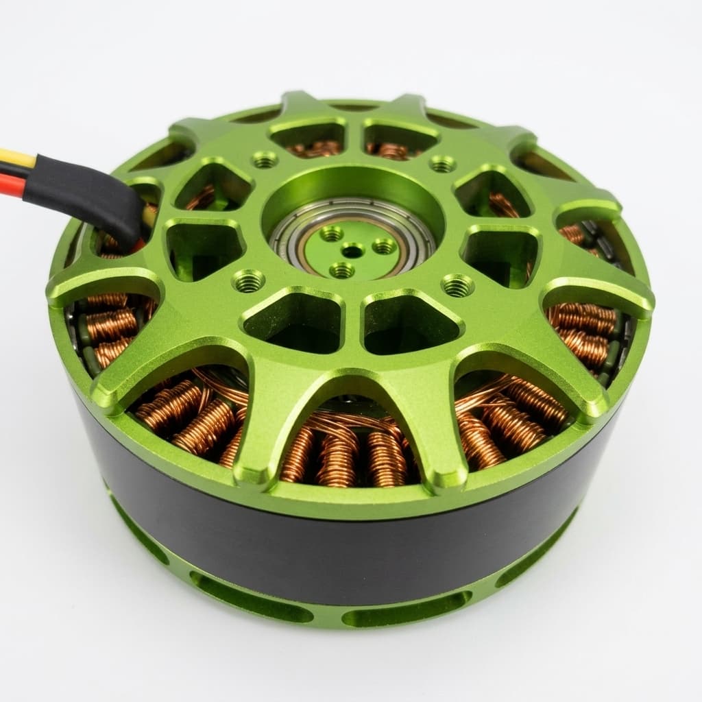
System boundary
The motor-only number is not enough
A credible 1000 hp AFPM review keeps peak output separate from continuous duty and includes the non-motor hardware that makes the operating point usable.
Evidence and method
Traceable Benchmarks, Dates, and Assumptions
The calculator is a feasibility screen, not a supplier guarantee. Use the public benchmarks below as boundary markers, then request platform-specific dyno data before purchasing or freezing a design.
Source-backed 750 kW-class Benchmarks
| Source | Date | What it supports | Confidence |
|---|---|---|---|
| YASA prototype release | October 22, 2025 | 750 kW peak, 12.7 kg mass, 59 kW/kg peak density, with 350-400 kW estimated continuous potential. | High for the public prototype claim; medium for continuous power because it is presented as an estimate. |
| YASA 750R product data | Public data checked July 25, 2026 | Production-class axial flux reference around 200 kW peak, 700 Nm peak, 98 mm axial length, and direct liquid cooling assumptions. | High for published product envelope; not a 1000 hp continuous-power proof. |
| Fraunhofer IISB aviation motor release | April 15, 2026 | 750 kW rated aviation research motor at 21,000 rpm, about 8 kW/kg, direct oil spray cooling, and four-section stator architecture. | High for the research demonstrator benchmark; platform integration still application-specific. |
Calculator Assumptions
| Parameter | Value | Boundary |
|---|---|---|
| Power target | 1000 hp = 745 kW mechanical output | The calculator uses 745 kW as the output ceiling before inverter, cable, pump, and gearbox losses. |
| Peak torque screen | 2000 Nm ceiling | Below about 3557 rpm, the torque ceiling limits power before the 745 kW point is reached. |
| Current estimate | 95% motor efficiency | DC current is calculated as output power divided by bus voltage and efficiency; real systems require inverter maps. |
| Thermal load | 39 kW heat at 95% efficiency | At 97% efficiency the motor still rejects about 23 kW, so continuous duty depends on coolant flow and winding temperature rise. |
Benchmark Interpretation
The YASA prototype is useful for peak power-density ceiling discussion. The Fraunhofer IISB machine is useful for aviation-grade continuous-power architecture discussion. The 750R reference is useful for understanding how lower-power production axial flux motors expose cooling, torque, and package constraints.
None of those public references alone proves that a given vehicle, aircraft, vessel, or industrial machine can use a continuous 1000 hp axial flux motor without added system mass and validation work.
Application screen
Where a 1000 HP AFPM Target Makes Sense
Use the calculator first, then compare the result with the application checks below. The right answer changes sharply between a short peak burst and continuous S1 operation.
Minimum Supplier Data Pack
Before treating any 1000 hp AFPM as viable, request a torque-speed map, peak-duration definition, continuous-duty map, coolant inlet temperature and flow, winding temperature limits, rotor overspeed evidence, inverter requirements, and full system mass.
| Application | Likely fit | Pass condition | Primary risk |
|---|---|---|---|
| Hypercar or racing burst | Strong peak-power fit | Peak duration, 800-1000 V bus, inverter phase split, and stator cooling can be validated on a dyno. | Thermal soak over repeated acceleration and track-lap duty cycles. |
| eVTOL or aviation propulsor | Possible only with redundant architecture | Continuous cruise, takeoff reserve, rotor containment, cooling failure modes, and certification margins are documented. | Mass growth from redundancy, containment, coolant, and certification hardware. |
| Marine pod or high-speed vessel | Viable when direct drive and flat package are valuable | S1 cooling loop, saltwater heat exchanger, IP sealing, bearing loads, and propeller curve are known. | Continuous thermal load and corrosion-proof cooling integration. |
| Industrial compressor or pump | Usually radial flux unless axial length is constrained | Duty cycle is intermittent or the supplier can prove continuous 745 kW thermal performance. | Cost and maintenance risk versus mature radial-flux alternatives. |
Risks and limits
What Can Break the Business Case
A high-power axial flux motor can look compelling on motor-only power density. These are the checks that keep the decision tied to production reality.
| Risk | Trigger | Mitigation |
|---|---|---|
| Bus current and inverter modules | DC current approaches or exceeds 1000 A | Use 800-1000 V architecture, parallel inverter legs, short busbars, and validated protection coordination. |
| Rotor containment | High RPM, large diameter rotor, or carbon sleeve stress margin is unknown | Require overspeed, burst, balance, and finite-element containment evidence before layout freeze. |
| Continuous winding temperature | Supplier only provides peak power without coolant flow and temperature-rise data | Ask for S1/S2 duty maps, coolant inlet conditions, winding sensor locations, and dyno test reports. |
| System mass creep | Cooling, inverter, gearbox, containment, and redundancy are excluded from the motor mass comparison | Compare complete propulsion-unit mass, not motor-only kW/kg. |
| Supplier manufacturability | Single prototype benchmark is treated as production availability | Separate prototype claims from production lead time, tooling, quality plan, and service support. |
Topology comparison
Axial Flux vs Radial Flux at 1000 HP
| Dimension | Axial Flux | Radial Flux | Decision note |
|---|---|---|---|
| Package | Flat, large diameter package that can fit wheels, pods, wings, or low-profile hulls. | Longer cylinder with smaller diameter; often easier to mount in conventional drivetrains. | Choose axial only when axial length is a hard constraint. |
| Torque density | Strong direct-drive potential if diameter and rotor stress are acceptable. | Mature, often gearbox-friendly architecture with broader supplier availability. | Compare complete drive-unit mass, not motor mass alone. |
| Thermal management | Needs close attention to stator, winding, magnet, and rotor heat paths at this power level. | Water-jacket and stator cooling approaches are more common and supplier-proven. | Continuous 1000 hp requires measured S1 evidence either way. |
| Supply risk | Higher custom engineering and validation dependency. | More mature industrial and traction supplier base. | Prototype benchmarks should not be treated as catalog availability. |
Related engineering pages
Continue the Feasibility Path
Use this primer to compare AFPM geometry, torque density, cooling paths, and application fit before committing to a 1000 hp envelope.
5 kW AFPM Motor CalculatorStart with a lower-power motor model to understand torque-speed behavior before scaling assumptions to megawatt-class peaks.
100 mm Axial Flux BLDC Generator ToolCheck smaller pancake-machine geometry and voltage tradeoffs for compact generator or motor-generator packaging studies.
Axial Flux Permanent Magnet MotorsReview the production-side AFPM product scope, torque-speed inputs, cooling options, and RFQ data needed for custom motor programs.
AFPM Motor OEM ManufacturingMap feasibility findings into prototype, pilot-build, quality, and supplier coordination steps before treating 1000 hp as a sourced part.
AFPM Design and Prototype SupportUse engineering-side prototype support when the 1000 hp concept still needs DFM, thermal, rotor, or validation-plan review.
10kW Axial Flux Motor Calculator & GuideEvaluate 10kW axial flux motors for light EVs, drones, and motorcycles.
20kW Axial Flux Motor Calculator & GuideEvaluate 20kW axial flux motors for light EVs, drones, and motorcycles.
FAQ
Common Questions
1000 HP Axial Flux Motor Feasibility
Can I buy an off-the-shelf 1000 hp axial flux motor today?
Usually no. Public 750 kW-class examples exist, but 1000 hp axial flux integrations are normally engineered around a platform, inverter, cooling system, shaft speed, and duty cycle. Ask suppliers to separate peak, short-duration, and continuous ratings.
Is 1000 hp the same as 745 kW?
Yes for this screening page. The calculator treats 1000 hp as about 745 kW mechanical output. Real pack power will be higher after motor, inverter, cable, pump, and gearbox losses.
What voltage is practical for a 1000 hp motor?
800 V is the practical starting point for many vehicle and aircraft concepts. At 745 kW and 95% motor efficiency, 800 V still implies roughly 980 A. Lower voltage makes current, cabling, and inverter packaging harder.
Can a 1000 hp axial flux motor run continuously?
Only if the motor, inverter, coolant loop, and mechanical package are designed for that continuous duty. Peak 1000 hp is much easier than S1 continuous 1000 hp because the motor must reject tens of kilowatts of heat without exceeding winding, magnet, bearing, or seal limits.
How should I compare axial flux and radial flux here?
Compare complete propulsion-system mass and package shape. Motor-only kW/kg can be misleading because axial flux may need special cooling, rotor containment, custom inverter packaging, and application-specific validation.
What information should I send for a feasibility review?
Send the duty cycle, torque-speed curve, bus voltage, cooling inlet temperature, allowed coolant flow, package diameter and axial length, shaft load, ambient conditions, IP rating, redundancy needs, and expected production volume.
Does stacking motors solve the 1000 hp problem?
Stacking can help distribute thermal and inverter load, but it also adds shaft, bearing, alignment, sealing, and control complexity. The stack still needs a validated continuous thermal map and fault strategy.
What is the biggest early design mistake?
Treating a peak-power press release as a continuous production specification. Freeze the duty cycle, coolant conditions, and full system mass before using any 1000 hp benchmark in a vehicle, aircraft, vessel, or industrial design.
Ready for 1000 HP Validation?
Send us your application profile, torque-speed curve, and cooling envelope. We will review feasibility and propose an OEM validation roadmap.
Inquiry Email
Please include application, peak/continuous torque, speed range, voltage/current limit, outer diameter, axial length, cooling method, quantity, and drawings or reference samples.
Instant Chat
WhatsApp Engineering Support
Share torque-speed, package, cooling, and sample quantity in the first message.