
Three-phase tooth coils · Reviewed
AFPM Motor Concentrated Winding: Tool & Guide
Check winding factor and electrical frequency, then compare the evidence and validation steps for your layout.
Winding checker
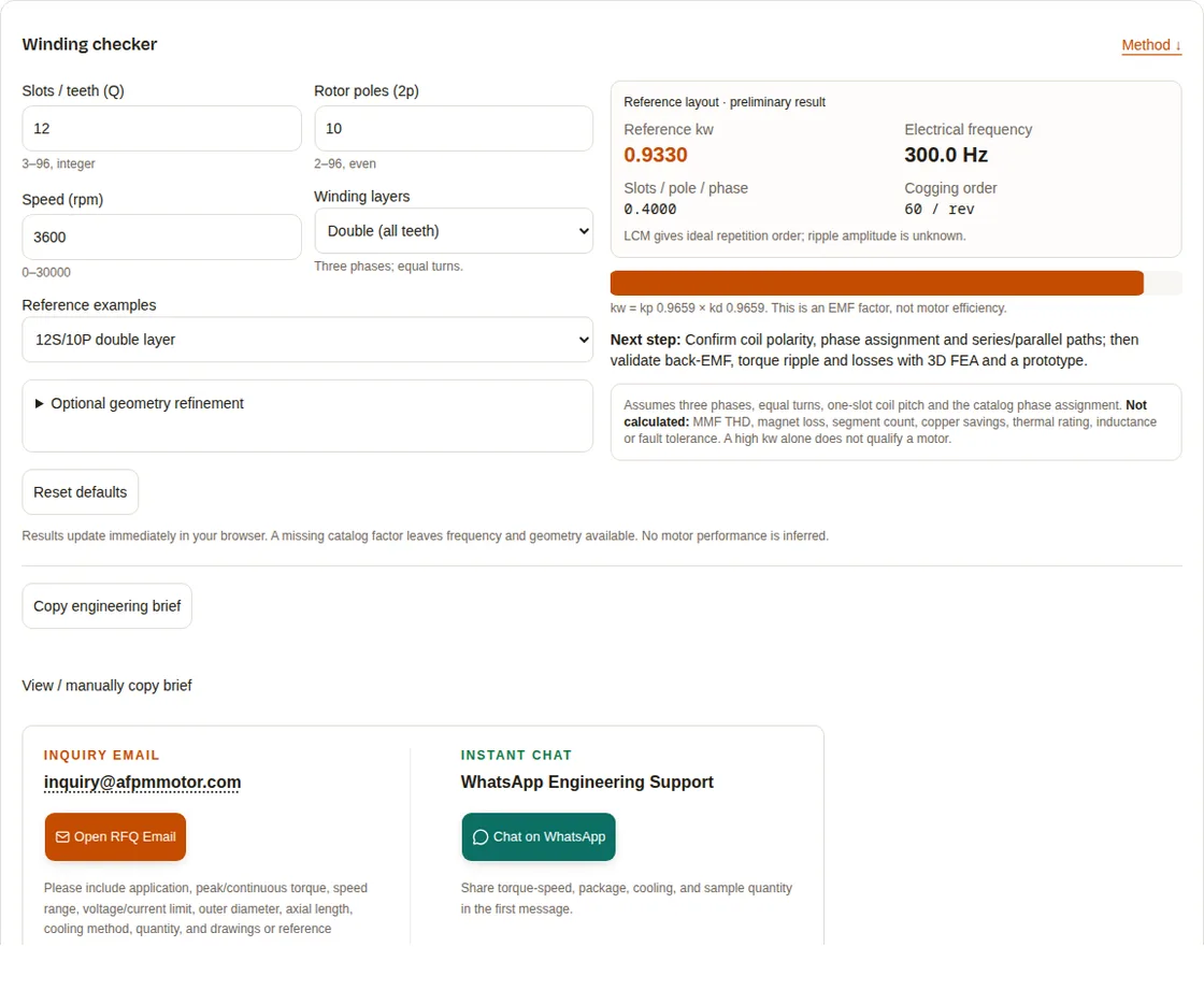
Method ↓Results update immediately in your browser. A missing catalog factor leaves frequency and geometry available. No motor performance is inferred.
View / manually copy brief
Inquiry Email
Please include application, peak/continuous torque, speed range, voltage/current limit, outer diameter, axial length, cooling method, quantity, and drawings or reference samples.
Instant Chat
WhatsApp Engineering Support
Share torque-speed, package, cooling, and sample quantity in the first message.
Published · Updated · Publisher: Magatom Dynamics Co., Ltd.. Analytical screening and software examples; no measured motor performance or independent certification is claimed.
1. What the screening result lets you decide
- Shortlist a connection, then validate it. The 12S/10P and 12S/14P double-layer reference layouts both have kw = 0.9330. This describes fundamental EMF utilization, not efficiency. Winding synthesis method.
- Account for frequency before increasing pole count. At 3,600 rpm, 10 poles give 300 Hz and 14 poles give 420 Hz, using fe = (2p)n/120. The higher frequency changes the inverter and loss-analysis requirements.
- Separate winding-factor quality from rotor heating. Nonworking spatial harmonics need their own loss analysis; a good fundamental factor cannot establish magnet temperature. Rotor harmonic-loss study.
- Use topology for packaging decisions. A yokeless segmented armature enables individually wound teeth, but retaining structure and cooling remain design tasks. YASA primary record.
| Known from this tool | Still unknown | Evidence needed next |
|---|---|---|
| q, electrical frequency and geometric pitches | Torque, voltage constant and continuous power | Turns, flux linkage, current loading and duty |
| Reference-layout kw, where cataloged | Balance of your actual series/parallel connection | Signed coil map and phase EMF sums |
| Ideal cogging repetition order | Peak cogging and loaded torque ripple | Geometry, tolerances, FEA and torque measurement |
| Coil-layer arrangement | Magnet loss, fault isolation and thermal rating | Field spectrum, inductance matrix and fault/thermal tests |
2. Method: coil pitch, phasors and reference layouts
Q denotes slots, 2p rotor poles and m phases. This tool fixes m = 3 and assumes identical turns, one-slot coil pitch and an iron-tooth stator. Double layer winds every tooth; single layer winds alternate teeth on an even-tooth ring. Changing polarity, pitch or parallel branches requires a new winding calculation. Cros & Viarouge.
kp = |sin(pπ / Q)|
kd = |Σ signed coil EMF vectors| / Σ |coil EMF|
kw = kp × kd
fe = (2p) × rpm / 120
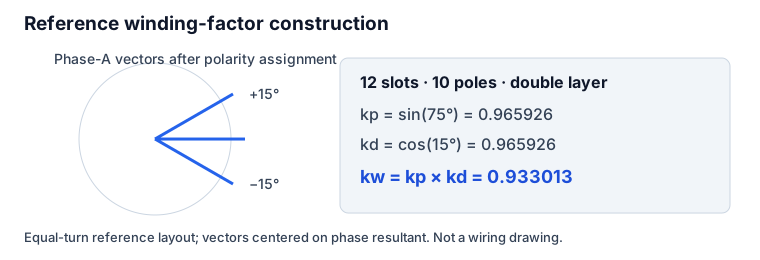
For the 12S/10P double-layer reference, coil phasors assigned to phase A resolve to ±15° about its resultant: kp = sin(75°), kd = cos(15°), so kw = 0.9330127. The alternate-tooth reference has aligned phase-A EMFs, kd = 1, and kw = 0.9659258. Each other phase must have equal magnitude and be displaced by 120°. These are ideal connection calculations, not measured motor data.
3. Slot/pole catalog: compare like-for-like layouts
Calculated reference factors below use the method above. The 9-slot family uses phase-coil angles 0°, +20° and −20° after polarity assignment. Repeated spatial layouts retain their factor. A dash means the single-layer connection is not cataloged here; it does not certify impossibility. See Salminen’s thesis for published winding-factor context, matching layer and connection before comparison.
| Slots / poles | q | kw double | kw single | Ideal LCM / rev |
|---|---|---|---|---|
| 9 / 8 | 0.3750 | 0.9452 | — not cataloged | 72 |
| 9 / 10 | 0.3000 | 0.9452 | — not cataloged | 90 |
| 12 / 8 | 0.5000 | 0.8660 | 0.8660 | 24 |
| 12 / 10 | 0.4000 | 0.9330 | 0.9659 | 60 |
| 12 / 14 | 0.2857 | 0.9330 | 0.9659 | 84 |
| 18 / 14 | 0.4286 | 0.9019 | — not cataloged | 126 |
| 18 / 16 | 0.3750 | 0.9452 | — not cataloged | 144 |
| 24 / 20 | 0.4000 | 0.9330 | 0.9659 | 120 |
Selection rule: compare electrical frequency at the same required mechanical speed, then evaluate harmonic fields, inverter voltage margin, manufacturability and ripple. The highest kw or LCM is not automatically the best machine.
4. Concentrated versus distributed: packaging and loss trade-offs
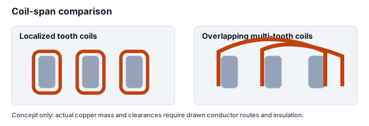
Nonoverlapping tooth coils reduce winding crossings and can simplify segmented-coil production. A distributed arrangement offers different spatial filtering. A useful comparison fixes active loading and operating duty before comparing drawn mean turn length and losses. Neither architecture has a universal copper-saving percentage. AFPM construction context.
| Dimension | Tooth-coil concentrated | Distributed / overlapping | How to compare |
|---|---|---|---|
| End turns | Localized coil routing | Coils span multiple teeth | Draw both layouts at equal active turns and conductor area |
| Harmonics | Nonworking spatial waves may be significant | Spatial distribution can filter selected waves | Compare winding spectra and rotor-frame fields |
| Production | Individual bobbins may simplify assembly | Insertion and crossings require clearance | Costed tooling, joining and insulation process |
| Failure behavior | Separation may help localize faults | Overlap can complicate separation | Fault-current model and validated protection |
5. Stator topology: what transfers to an AFPM disc
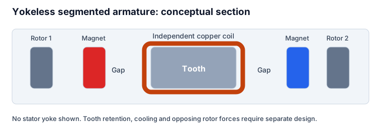
The original YASA work describes a yokeless segmented armature. Its individually wound teeth fit the tooth-coil concept, while retention and thermal paths must be designed around the dual-rotor structure. Current commercial slot counts, conductor fill, segmentation and cooling ratings are not established by this source. Woolmer & McCulloch (2007).
| Topology | Useful characteristic | Check before selection | Tool scope |
|---|---|---|---|
| Yokeless segmented armature | Individual wound teeth without stator yoke | Rotor balance, tooth retention, cooling and axial loads | Reference tooth-coil factors only |
| Slotted stator with yoke | Continuous magnetic and structural return path | Yoke saturation, mass and thermal path | Match actual pitch and connection |
| Coreless / PCB | Different conductor and magnetic circuit | Trace/coil path, air-gap field and thermal limits | Outside this iron-tooth catalog |
6. Spatial harmonics: use the rotor frame correctly
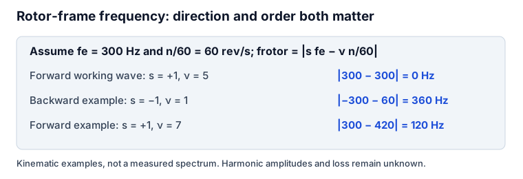
A working wave has p pole pairs; other signed spatial waves can move relative to the rotor. For positive rotor rotation n and a harmonic of ν pole pairs with direction s = ±1, its rotor-frame frequency is frotor = |s fe − ν n/60|. For a forward working wave ν = p, this is zero. Direction and order both matter. The tool does not infer a spectrum from slots alone. Pyrhönen et al. (2012).
As an illustrative kinematic check, at 3,600 rpm and fe = 300 Hz, a backward ν = 1 wave gives |−300 − 60| = 360 Hz. It is not a 1,500 Hz field merely because the working wave has five pole pairs. This example specifies direction; it makes no claim about the wave amplitude in a particular layout.
7. Magnet eddy currents: test segmentation rather than prescribing it
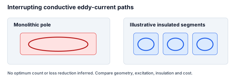
Magnet resistivity, dimensions, harmonic flux, electrical insulation between pieces and inverter spectrum all affect loss. A rotor-loss model needs these inputs; the calculator supplies none of them. Compare monolithic and segmented candidates under the same excitation and cooling boundary. Validated loss-model study.
Skin depth δ = √(ρ/(π f μ)) compares diffusion length with conductor dimensions. Segmentation can reduce circulating paths, but frequency and geometry can also produce a segmentation anomaly. Do not transfer an inverse-square trend to every rotor or promise a fixed percentage reduction. Plait & Dubas (2022).
8. Disc geometry and copper accounting
The active radial span is (OD − ID)/2, not OD − ID. At radius r, slot pitch is 2πr/Q. If tooth width is constant, available slot width varies with radius. Check the inner-radius bend and clearance before committing a rectangular bobbin; report net copper area after insulation and potting allowances.
For the baseline OD/ID 280/180 mm, radial span is 50 mm and mean diameter is 230 mm. The 12-slot mean tooth pitch is 60.21 mm and 10-pole pitch is 72.26 mm. Neither pitch defines the actual tooth width. To compare copper, use mass = density × total conductor area × actual mean turn length, including joints and leads. The checker does not calculate savings from assumed tooth-width multipliers.
| Quantity | Baseline value | Decision boundary |
|---|---|---|
| OD / ID | 280 / 180 mm | Illustrative input dimensions |
| Active radial span | 50.00 mm | Not the diameter difference |
| Mean tooth / pole pitch | 60.21 / 72.26 mm | Pitch is not tooth width or coil clearance |
| Copper mass / end-turn overhang | Unknown | Need conductor area, turn count and drawn routing |
9. Isolation, field weakening and fault limits
Separate bobbins can support physical separation, yet magnetic coupling, interturn faults and thermal propagation still require assessment. A layer choice cannot establish galvanic independence of two inverters or a remaining torque percentage. Review the actual neutral connections, protection and phase isolation architecture.
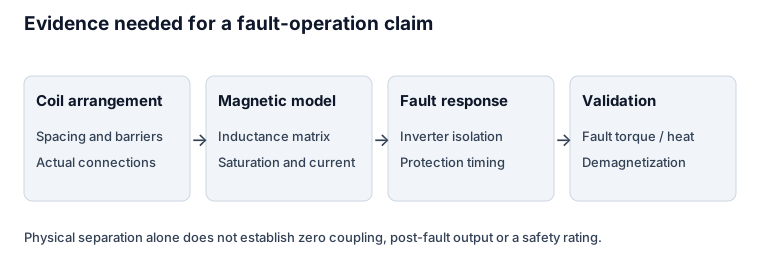
The characteristic current ψm/Ld is useful in a defined machine model, but neither quantity is known here. It cannot establish a constant-power speed range, a bounded transient short-circuit current, or freedom from irreversible demagnetization. Require temperature-dependent material data and fault analysis before making those decisions.
10. Conductor choice and manufacturing cost
Screen manufacturability alongside losses. A large wire cross-section may improve DC resistance while increasing AC losses or bend difficulty. Cooling and duty determine acceptable current density; insulation temperature class alone is not a permissible coil hotspot specification.
| Conductor | Potential benefit | Cost / design risk | Evidence to request |
|---|---|---|---|
| Round enameled wire | Flexible winding and accessible tooling | Packing variation; joining and local proximity loss | Cross-section sample, resistance and AC-loss estimate |
| Rectangular / preformed copper | Orderly packing in a compatible slot | Bend strain, enamel damage, tooling and AC loss | Bend trials, insulation checks and net slot area |
| Transposed / Litz construction | Can reduce selected AC-loss components | Termination labor, strand insulation and reduced net copper area | Current-spectrum loss comparison including terminations |
11. Validation plan and standards boundary
Standards checked 2026-10-24: IEC 60034-15:2025 replaces the 2009 edition and excludes converter-fed windings. For Type I insulation in PWM-fed machines, review IEC 60034-18-41 and its applicable amendments. Agree classification, terminal waveform, sample type and test limits with the responsible engineer. The following is a project planning checklist, not a normative acceptance specification. IEC 60034-15; IEC 60034-18-41.
| Stage | Record / measure | Acceptance basis still needed |
|---|---|---|
| Coil and insulation process | Conductor damage, insulation build, surge/PD tests where applicable | Qualified insulation system, converter stress and agreed test procedure |
| Winding continuity and resistance | Four-wire resistance, temperature, phase/branch connection | Drawing, temperature correction and allocated balance tolerance |
| Isolation | Specified dielectric / insulation test and fixture | Insulation class, creepage, environment and approved test voltage |
| Inductance and coupling | Position- and current-dependent phase matrix | Control model, saturation and fault-current requirements |
| Back-EMF, torque and temperature | Phase waveform, ripple, duty and hotspots | Product specification and calibrated dynamometer results |
Before serial tooling, resolve the inner-radius coil clearance, tooth retention, magnet bonding and potting process. Quote setup, scrap, inspection and rework separately from recurring part cost. Public evidence here does not establish a supplier MOQ, lead time or commercial teardown specification.
12. Five illustrative screening scenarios
These are input-driven exercises, not measured product case studies. Use the matching tool preset to reproduce each result. Torque, efficiency, temperature, flight capability and manufacturing savings are unknown.
1. 12S/10P double layer
Assume 3600 rpm, OD/ID 280/180 mm.
Method: q = Q/((2p) × 3), fe = (2p)n/120; apply the catalog connection.
q 0.4000 · kw 0.9330 · 300.0 Hz · LCM 60
For a traction study, add the voltage envelope, current limit and cooling duty before sizing turns.
2. 24S/20P double layer
Assume 2400 rpm, OD/ID 240/160 mm.
Method: q = Q/((2p) × 3), fe = (2p)n/120; apply the catalog connection.
q 0.4000 · kw 0.9330 · 400.0 Hz · LCM 120
For a propulsor study, evaluate harmonic rotor losses and retention before assessing mass or continuous output.
3. 18S/16P double layer
Assume 1200 rpm, OD/ID 160/100 mm.
Method: q = Q/((2p) × 3), fe = (2p)n/120; apply the catalog connection.
q 0.3750 · kw 0.9452 · 160.0 Hz · LCM 144
For a joint actuator study, measure cogging and loaded ripple; LCM does not establish haptic smoothness.
4. 12S/14P double layer
Assume 2800 rpm, OD/ID 220/140 mm.
Method: q = Q/((2p) × 3), fe = (2p)n/120; apply the catalog connection.
q 0.2857 · kw 0.9330 · 326.7 Hz · LCM 84
Compare against 12S/10P at the same speed, including increased electrical frequency and inverter limits.
5. 12S/10P single layer
Assume 1800 rpm, OD/ID 180/110 mm.
Method: q = Q/((2p) × 3), fe = (2p)n/120; apply the catalog connection.
q 0.4000 · kw 0.9659 · 150.0 Hz · LCM 60
Compare phase isolation and harmonic losses against double layer; higher kw does not establish fault capability.
13. Frequently asked decision questions
Layout decisions
What is concentrated winding in an AFPM motor?
Each tooth coil spans one slot pitch, avoiding overlapping multi-tooth end windings. Fractional-slot layouts have q = Q/(2p × m) below one. Compact coils can help packaging, but end turns remain finite and winding choice alone does not establish motor efficiency.
Why compare 12-slot/10-pole and 12-slot/14-pole layouts?
The catalog double-layer connections both give kw = 0.9330. At equal rpm the 14-pole option has higher electrical frequency: seven electrical cycles per revolution rather than five. Compare inverter frequency, harmonic losses and mechanical constraints before choosing.
How is the winding factor calculated?
For a one-slot tooth coil, kp = |sin(pπ/Q)|. Vector-sum the signed coil EMFs of each phase to obtain kd, then kw = kp × kd. The tool uses explicit reference phase-belt layouts; slots and poles alone do not uniquely define a winding connection.
Can 9 slots use an alternate-teeth single-layer winding?
A closed nine-tooth ring cannot alternate wound and unwound teeth throughout. This tool rejects that arrangement. Use a double-layer 9S/8P layout or a cataloged even-slot example such as single-layer 12S/10P.
Why does a custom combination show Not assessed?
It has no reference phase assignment in this catalog. The tool still calculates q, electrical frequency, ideal repetition order and geometry for valid inputs. Supply a coil connection drawing for a phasor balance check, or select a reference example.
Losses and operating limits
Does a high cogging LCM guarantee smooth torque?
No. LCM(Q, 2p) gives an ideal geometric repetition order, not cogging amplitude or loaded torque ripple. Magnet arc, slot openings, eccentricity, tolerances and saturation still need field analysis and testing.
Does the tool calculate MMF THD or magnet loss?
No. These require a signed winding-function spectrum, current waveform, air-gap harmonic fields, magnet material and dimensions, and a loss model. A universal THD percentage or segmentation count cannot be inferred from q and speed.
How is rotor-relative harmonic frequency found?
Use frotor = |s × fe − ν × n/60| for a spatial wave of ν pole pairs with direction s = +1 or −1, using a consistent positive rotor direction. A forward working harmonic ν = p is synchronous and gives zero rotor-relative frequency.
How many magnet segments should I specify?
Compare segment directions and counts in an electromagnetic loss model using actual magnet resistivity, coating and PWM spectrum. Segmentation can add adhesive gaps, assembly cost and retention constraints; no fixed speed or electrical-frequency threshold selects an optimum.
Does single-layer winding make a motor fault tolerant?
Physical coil separation can help isolation, but residual magnetic and thermal coupling remains. Fault operation needs the full inductance matrix, short-circuit and demagnetization analysis, inverter isolation strategy and fault tests. The tool assigns no aerospace or safety rating.
Geometry and manufacturing
Can copper savings be inferred from slots and poles?
No. Compare measured or drawn mean turn lengths with equal active turns, conductor area and target electromagnetic loading. A shorter end turn does not by itself quantify total copper mass, resistance, axial envelope or efficiency.
What does the optional geometry calculation mean?
The active radial span is (OD − ID)/2. At mean diameter Dm = (OD + ID)/2, tooth pitch is πDm/Q and pole pitch is πDm/(2p). These are geometric checks, not tooth-width, clearance or end-turn predictions.
When should I choose rectangular copper, round wire or Litz?
Compare usable slot area after insulation, bend radius, manufacturability, AC resistance over the actual current spectrum, cooling and cost. Electrical frequency alone cannot make Litz mandatory or establish a universal fill-factor target.
Can the catalog be used for a coreless PCB winding?
No. A PCB or air-cored coil has its own conductor paths, coil pitch and connection. Use its winding function to calculate the factor. A coreless alternative is discussed in the report but is outside this iron-tooth calculator.
Validation and sourcing
Which insulation standard should a PWM-fed AFPM project review?
Start with the insulation-system classification and converter terminal stresses. IEC 60034-18-41 addresses Type I converter-fed systems. IEC 60034-15:2025 excludes converter-fed coils, so it cannot support a blanket 2.5 kV surge acceptance rule for traction motors.
What should an OEM include in the engineering brief?
Include slot/pole count, layer and coil connection, turns and conductor details, torque-speed duty, DC bus and inverter limits, dimensions, cooling and environment, required fault behavior, quantity and acceptance criteria. The copy function exports the screening inputs and limits.
Are the worked scenarios measured motor performance?
No. They are illustrative calculations from the stated inputs. Frequencies, q and reference winding factors are reproducible; torque, efficiency, cooling capability, lead time and production cost remain unverified.
What if JavaScript or clipboard access is unavailable?
Without JavaScript, the fixed baseline result, catalog, formulas and inquiry links remain readable, and input editing is disabled. If clipboard access fails, the tool exposes a selectable brief for manual copying. You can also send a coil drawing for review.
14. Primary sources, scope and review date
Reviewed 2026-10-24. Source links identify the underlying work or publisher scope statement. Some full texts require access; the sources do not verify proprietary product details or certify this checker.
- Gieras, Wang & Kamper — Axial Flux Permanent Magnet Brushless Machines
Springer, 2nd edition, 2008
Supports: AFPM topology, fabrication and cooling context.
Boundary: Book overview is public; detailed chapters may require access. No supplier performance is inferred.
- Cros & Viarouge — Synthesis of high performance PM motors with concentrated windings
IEEE Transactions on Energy Conversion 17(2), 248–253, 2002
Supports: Reference method for three-phase concentrated winding synthesis.
Boundary: A winding method is not a validated AFPM product. Catalog values here are analytical reference layouts.
- Salminen — Fractional slot permanent magnet synchronous motors for low speed applications
LUT doctoral thesis, 2004
Supports: Fractional-slot winding factors and harmonic context.
Boundary: Layer, pitch and phase connection must match before transferring a published factor. Repository may challenge automated access.
- Woolmer & McCulloch — Analysis of the yokeless and segmented armature machine
IEMDC 2007, pp. 704–708; DOI 10.1109/IEMDC.2007.382753
Supports: Primary YASA topology record: independent wound segments without a stator yoke.
Boundary: Does not disclose current commercial models, coil fills or fault certification.
- Bianchi & Bolognani — Design techniques for reducing the cogging torque in surface-mounted PM motors
IEEE Transactions on Industry Applications 38(5), 1259–1265, 2002
Supports: Cogging mitigation depends on geometry and can affect back-EMF.
Boundary: Repetition order alone cannot predict amplitude. University record provides abstract and DOI 10.1109/TIA.2002.802989.
- Pyrhönen et al. — Harmonic Loss Calculation in Rotor Surface Permanent Magnets—New Analytic Approach
IEEE Transactions on Magnetics 48(8), 2012; DOI 10.1109/TMAG.2012.2190518
Supports: Harmonic-dependent rotor loss model compared with 3D FEA and measurements, including an axial-flux machine.
Boundary: Loss calculation needs harmonic flux and magnet geometry/material inputs absent from this screening tool.
- Plait & Dubas — Volumic Eddy-Current Losses in Conductive Massive Parts with Experimental Validations
Energies 15(24), 9413, 2022
Supports: Skin-depth effects and conditions under which segmentation can increase losses.
Boundary: Experimental conductive-part geometry is not a universal NdFeB AFPM rotor benchmark.
- IEC 60034-15:2025 — Impulse voltage withstand levels of form-wound stator coils
Edition 4.0, published 2025-06-06; checked 2026-10-24
Supports: Supersedes the 2009 edition; covers grid-connected form-wound coils and excludes converter-fed coils.
Boundary: Cannot justify a universal surge voltage for inverter-fed AFPM traction windings.
- IEC 60034-18-41:2014+AMD1:2019 CSV — Type I converter-fed insulation systems
Edition 1.1; includes December 2020 corrigendum; checked 2026-10-24
Supports: Qualification and quality-control scope for Type I insulation under voltage-source PWM converters.
Boundary: Applicability and test levels require the actual insulation system and terminal waveform; not a general motor certification.