Engineering estimates · Reviewed 2026-11-02

AFPM Motor Controller Tuning

Estimate FOC PI gains, voltage demand and PWM ripple. Edit inputs, then plan bench validation.

Edit motor inputs

FOC tuning calculator

Interactive controls load with JavaScript; default estimates are shown below.
Current target: 1400 Hz · Voltage demand: 108.4% of linear SVPWM limit. Rated point exceeds voltage limit. Reduce speed/load and review the operating map.

Illustrative preset; verify on bench. All numeric fields are required; ranges are shown in the error summary if exceeded. Estimates assume phase-neutral parameters, peak dq current, Id = 0 and one current update per PWM period. Method, limits and evidence

Choose an illustrative application preset

1. Motor Electromagnetics & Operating Boundary

2. Inverter Power Stage, PWM & Dynamic Filter Constraints

3. Estimated gains & operating checks

Current Target (fc)
1400 Hz

τe,q = 2473.7 µs (8796 rad/s)

Continuous Kp_q / Ki_q
0.82686719 / 334.26546

Pole-zero cancel (Kp/Ki = 2473.7 µs)

Current Ripple (ΔI_pp)
86.44 A (21.8%)

PWM for illustrative 12% target: 36.4 kHz

Characteristic Current (Ich)
756.1 A

Magnet safety: UNVERIFIED

Field-weakening screen: Full flux cancellation lies outside the peak current circle. This does not rule out partial field weakening. Maximum speed and demagnetization safety cannot be inferred from Ich alone; obtain the motor Id-versus-temperature limit and voltage/current operating map.

Before applying gains: Kp is V/A; continuous Ki is V/(A·s). The Euler integral increment is Ki/fPWM. Vendor normalization and Tustin coefficients differ. Speed-loop lag assumes 1/ωcc + 2Tpwm (214 µs); actual filters and speed task timing may require slower gains.

Ripple is a half-duty estimate in A peak-to-peak, divided by √2 × phase RMS for the percentage. The 12% target is an illustrative design choice. Dead-time voltage is a fundamental peak error estimate, not sixth-harmonic amplitude or a timing-derived electrical phase lag. Magnet temperature and maximum safe speed are unknown.

Next: validate on the commissioning checklist

Current loop SI gains & decoupling

Control ParameterAnalog ContinuousEuler accumulator (Ts = Tpwm)
d-Axis Proportional (Kp_d)0.721309670.72130967
d-Axis Integral (Ki_d)334.265460.016713273
q-Axis Proportional (Kp_q)0.826867190.82686719
q-Axis Integral (Ki_q)334.265460.016713273
d-q Decoupling Factor (ωe·L)D: 0.51187016 V/A | Q: 0.44652504 V/A
Back-EMF (V peak); total demand below337.61649 V (Demand: 108.4%)

Speed Loop (Symmetric Optimum) & Inverter Distortion

Dynamic MetricTuned ValueEngineering Context
Speed Loop Crossover Estimate266 HzSymmetric optimum (a = 2.8)
Speed Proportional Kp_v78.626497 A_pk/(rad/s)Kt = 0.744 Nm/A_pk
Speed Integral Ki_v46933.692 A_pk/radIntegral reset Ti = 1.7 ms
Dead-Time Voltage Error7.4 V0.9% PWM period at 20 kHz
ADC selectionNot determinedNeeds shunt/gain, noise, effective bits and sampling-window measurements.

Position Angle Offset Sensitivity

With 8 pole pairs, 1° mechanical error equals 8° electrical error!

Illustrative offset sweep; set acceptance limits from torque and Id budgets
Electrical Error (Δθe)Equivalent Mechanical Error (Δθm)Torque Retention cos(Δθe)Unwanted |Id| (sign depends on offset)Unwanted Torque Penalty
0.5° elec0.063° mech100.0%3.5 A0.0 Nm
1.5° elec0.188° mech100.0%10.4 A0.1 Nm
3.0° elec0.375° mech99.9%20.7 A0.4 Nm
5.0° elec0.625° mech99.6%34.5 A1.1 Nm
8.0° elec1.000° mech99.0%55.1 A2.9 Nm
12.0° elec1.500° mech97.8%82.3 A6.4 Nm

Engineering Diagnostics & Commissioning Boundaries

High Electrical Frequency at Rated Speed
Rated electrical frequency is 867 Hz due to the high pole count (16 poles). Controller calculation latency and ADC sample-and-hold delays consume significant electrical phase angle.
Recommended Action: Review dq feedforward and compensate measured angle/sampling latency using the inverter control design; validate at low energy first.
Rated Point Exceeds Linear SVPWM Voltage Limit
Voltage utilization reaches 108.4% at rated speed and torque, in the Id = 0, steady-state model. Above 100%, this operating point is unavailable in linear SVPWM.
Recommended Action: Reduce the requested speed/load or review a hardware-rated higher bus voltage. Evaluate field weakening only with manufacturer-approved negative-Id and mechanical limits.
Inverter Dead-Time Distortion Risk
At 20 kHz, a 450 ns dead time causes 7.4 V of estimated fundamental peak phase-voltage error. Additional harmonics can produce torque ripple; this value is not the sixth-harmonic amplitude.
Recommended Action: Verify dead time against device/driver delays across voltage, current and temperature; assess polarity-aware compensation without bypassing shoot-through protection.

Inquiry Email

[email protected]

Please include application, peak/continuous torque, speed range, voltage/current limit, outer diameter, axial length, cooling method, quantity, and drawings or reference samples.

Instant Chat

WhatsApp Engineering Support

Share torque-speed, package, cooling, and sample quantity in the first message.

1. Decisions before tuning

What the tool can support, and what needs more evidence
DecisionKnown relationshipNext action / evidence
Start current PI designKp = L·ωcc; Ki = Rs·ωcc for a decoupled linear plant.Use measured phase parameters; validate delay and saturation (TN111).
Check the rated pointRequired peak voltage compared with Vdc/√3; demand is not capped at 100%.Above 100%: reduce speed/load or review an approved operating map (TN145).
Separate speed and current loopsInclude current-loop response in outer-loop lag.Measure speed-task/filter delay; check mechanical resonances (TN114).
Review weakeningIch = ψf/Ld screens complete flux cancellation only.Obtain negative-Id/temperature and mechanical limits (Microchip).

Evidence: Imperix TN111 — Field oriented control of PMSM · Imperix TN114 — Motor speed control · Imperix TN145 — Space Vector Modulation · Microchip — Equation-based Flux Weakening

2. Method, conventions and unknowns

This deterministic screening model assumes a sinusoidal three-phase PMSM, constant phase-neutral Rs/Ld/Lq/ψf, amplitude-invariant peak dq current, steady motoring at Id = 0, linear SVPWM and one current-control update per PWM period. Presets are synthetic examples, not vendor specifications or measured installations.

Calculation contract — reviewed 2026-11-02
OutputMethod / unitsLimitation
Current gainsKp V/A, Ki V/(A·s); Euler increment Ki/fPWM.No Tustin or vendor per-unit/register conversion.
Voltage demandvd = −ωeLqiq; vq = Rsiq + ωeψf; iq = √2·Irms.Excludes bus sag, semiconductor drops and transient margin.
Speed gainsKt = 1.5pψf; TΣ = 1/ωcc + 2Tpwm.Transport = 1.5Tpwm; feedback = 0.5Tpwm are assumptions. Actual speed sampling, filtering, compliance and saliency are not identified.
Ripple / PWM targetΔIpp ≈ Vdc/(4LqfPWM); target = 12% of √2·Irms.Half-duty approximation; modulation/duty and differential inductance change ripple. Target is illustrative, not a standard.
Magnet / speed / ADC limitsUnknown — data not supplied.Needs magnet curves, rotor temperature, speed rating, current sensing chain and noise measurements.

Evidence: Imperix TN111 — Field oriented control of PMSM · Imperix TN114 — Motor speed control · Microchip — Field Oriented Control application overview

3. FOC signal flow and feedforward

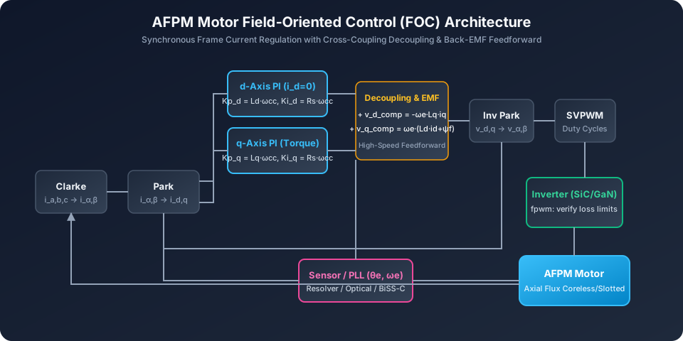
FOC signal flow
Add vd_ff = −ωeLqiq and vq_ff = +ωe(Ldid+ψf) to PI outputs with the transform convention used here. Synchronous current sampling reduces switching contamination; it does not remove physical ripple. Diagrams are schematic, not measured curves. On small screens, scroll the diagram horizontally.

Feedforward improves tracking when its parameters and signs match the plant. It cannot increase the available inverter voltage. Clamp the voltage vector and coordinate anti-windup with current limits.

Evidence: Imperix TN111 — Field oriented control of PMSM · Imperix TN145 — Space Vector Modulation

4. Tune the measured motor, not the topology label

Application-specific priorities; no universal inductance or CPSR guarantees
ApplicationCheck firstWhy it changes the decision
Coreless / low-inductance AFPMDifferential L, ripple, sampling window, inverter loss.A high PWM target may exceed practical switching/thermal limits.
Slotted traction AFPMRated-point voltage, resolver timing, saturation maps.High electrical speed and load can exhaust voltage headroom.
Robotic jointOffset error, total load inertia, fixture resonance.Precision may require slower speed control and better sensing.
Direct-drive generationDC-link energy sink, load rejection, current protection.A motoring PI estimate does not design the outer DC-link regulator.

Axial geometry alone does not set inductance, inertia or saliency. Compare measured Rs, Ld/Lq, ψf, pole pairs and inertia with your inverter. Electrical frequency is p·RPM/60 for both axial and radial PMSMs.

Evidence: Imperix TN111 — Field oriented control of PMSM · Imperix TN114 — Motor speed control

5. Sensor alignment and angle sensitivity

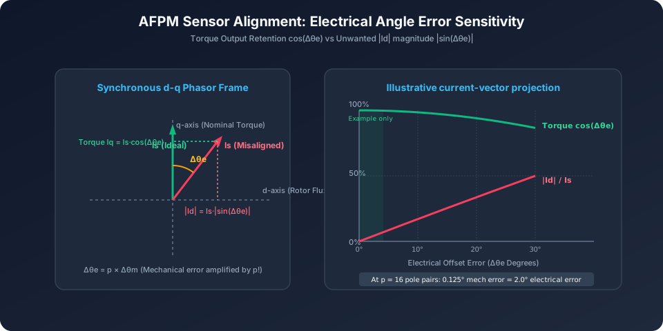
Electrical angle error sensitivity
Δθe = p·Δθm. At fixed current and ignoring reluctance torque, torque retention is cos(Δθe); unwanted |Id| is I·|sin(Δθe)|. Offset sign determines whether the component is magnetizing or demagnetizing. Diagrams are schematic, not measured curves. On small screens, scroll the diagram horizontally.

Calibrate a known stationary stator vector with verified phase sequence and sensor direction using the vendor procedure. Do not derive electrical zero from an assumed universal back-EMF crossing. Select an alignment tolerance from torque loss and allowed Id, then verify at low speed in both directions.

Evidence: Imperix TN111 — Field oriented control of PMSM

6. Current PI design and delay limits

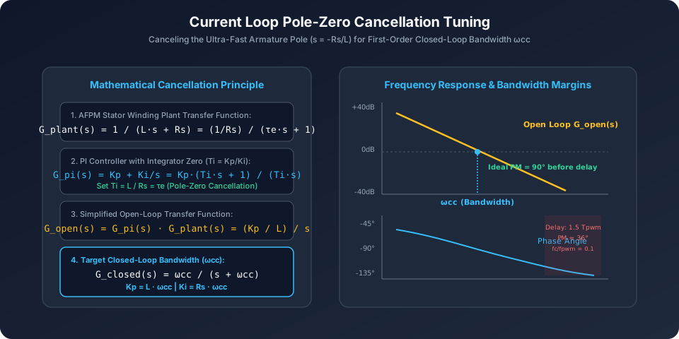
Ideal current-loop pole cancellation
For 1/(Ls+Rs), Kp = Lωcc and Ki = Rsωcc give Ti = L/Rs. The ideal cancelled open loop has 90° phase margin before delays. At fc/fPWM = 0.1, an assumed 1.5-period delay subtracts 54°, leaving 36° before other dynamics. Diagrams are schematic, not measured curves. On small screens, scroll the diagram horizontally.

Use the displayed SI gains as hypotheses for a current-limited step test. The Euler accumulator uses x[k+1] = x[k] + Ki·Ts·e[k]; voltage is Kp·e + x. For Tustin the integral increment uses Ki·Ts/2·(e[k]+e[k−1]). Both need anti-windup. Measure differential inductance over relevant bias, rotor angle and frequency; no fixed percentage change with frequency is assumed.

Evidence: Imperix TN111 — Field oriented control of PMSM · Imperix TN145 — Space Vector Modulation

7. Ripple, dead time and inverter tradeoffs

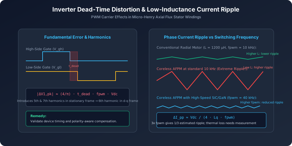
Dead-time and ripple schematic
Dead time causes a current-polarity-dependent average voltage error. A simple square-wave model gives fundamental peak error (4/π)tdeadfPWMVdc. Phase harmonics can contribute to sixth-order torque ripple; these are different quantities. Diagrams are schematic, not measured curves. On small screens, scroll the diagram horizontally.
Reproducible PWM comparison — synthetic 96 V, Lq = 18 µH, 120 A RMS
PWMΔIpp estimate% of 169.71 A continuous peakDecision
16 kHz83.33 A49.1%Compare ripple against measured loss/thermal budget.
32 kHz41.67 A24.6%Compare ripple against measured loss/thermal budget.
64 kHz20.83 A12.3%Check switching loss and inverter frequency rating.

Higher PWM trades smaller ripple for switching loss, cooling demand and EMI work. Series chokes add mass, resistance and voltage drop. Faster devices do not guarantee a particular dead time or bearing solution. Measure common-mode/shaft current and insulation stress before selecting filters or bearing mitigation. Rotor magnet heating requires harmonic-loss and thermal evidence; this model does not predict it.

Evidence: Imperix PN115 — Dead time selection for power modules

8. Weakening is a constrained operating map

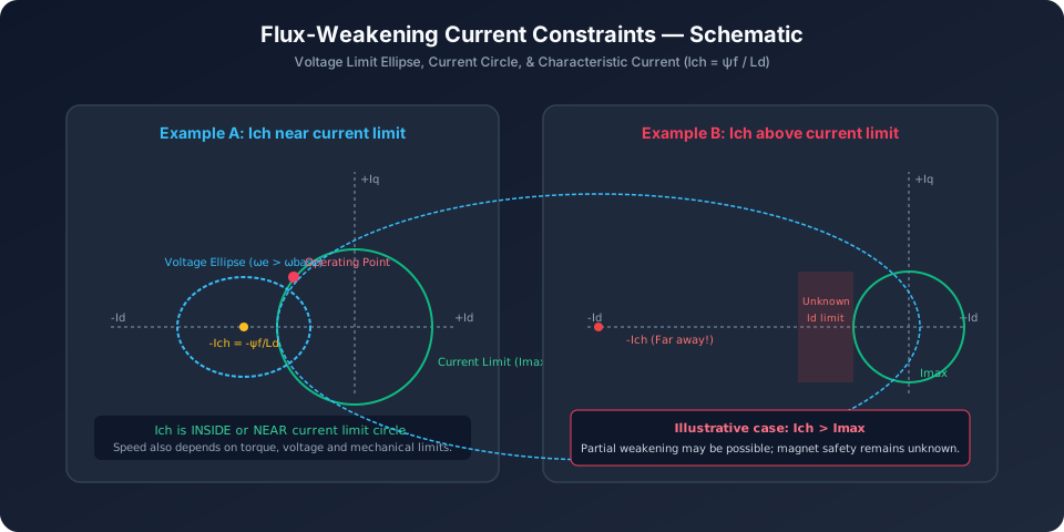
Voltage ellipse and current circle
Ich = ψf/Ld is the d-axis cancellation current in a linear model. Compare it with peak current on the same basis. At load, iq also uses the current budget; safe negative Id and maximum mechanical speed remain separate constraints. Diagrams are schematic, not measured curves. On small screens, scroll the diagram horizontally.

A large Ich can restrict weakening, but does not exclude partial speed extension. A small Ich does not prove magnet safety. Require id²+iq² ≤ Imax², vd²+vq² ≤ (Vdc/√3)², a manufacturer-approved negative-Id limit versus rotor temperature, and mechanical speed approval. Missing any of these leaves maximum safe speed unknown.

Evidence: Microchip — Equation-based Flux Weakening · Microchip — Field Oriented Control application overview

9. Keep the speed loop slower

TΣ = 1/ωcc + 2Tpwm; Kp = J/(a·TΣ·Kt); Ti = a²·TΣ; Ki = Kp/Ti; crossover estimate = 1/(2πaTΣ).

Here a is a symmetric-optimum design factor, not a damping ratio ζ. The assumed small-delay sum includes the inner current response plus illustrative transport/feedback timing; it does not identify a real speed controller. Use measured speed task period and filters, account for coupling resonance, and lower gains where needed. No fixed overshoot or phase-margin guarantee follows from a alone. Apply setpoint ramping and validate current limiting before load steps.

Evidence: Imperix TN114 — Motor speed control

10. Commissioning gates and recovery

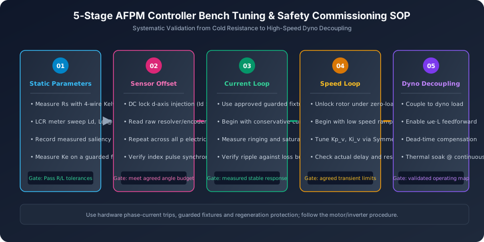
Five-stage commissioning checklist
Use a guarded fixture, a suitable energy sink for regeneration, hardware phase-current protection and the motor/inverter commissioning procedure. A current-limited DC supply alone cannot protect against local DC-link discharge or phase faults. Diagrams are schematic, not measured curves. On small screens, scroll the diagram horizontally.
  1. Identify phase parameters, winding connection and sensor mapping. If unknown, stop gain application and measure first.
  2. Verify phase sequence, current feedback polarity, offset and sensor direction with conservative limits and an unloaded guarded shaft.
  3. Measure d/q step responses at low energy. Reduce bandwidth if ringing, clipping or current reconstruction errors appear.
  4. Add slow speed control; verify ramping, saturation recovery, fault handling and fixture resonance before increasing load.
  5. Validate the speed/torque map, load rejection and thermal limits. Field weakening requires approved Id/temperature and mechanical limits.

Evidence: Imperix TN111 — Field oriented control of PMSM · Imperix TN114 — Motor speed control · Microchip — Field Oriented Control application overview

11. Inverter selection and handoff

Request written confirmation for the exact hardware and firmware revision
ItemAsk the supplierCost / mismatch risk
Frequency and current measurementAllowed PWM range, sampling windows and current-control update period for measured L.Switching losses, thermal derating or a new inverter/choke.
Position interfaceSensor electrical cycles, excitation, polarity, latency and supported speed.Interface changes and calibration time; no assumed YASA/EMRAX universal option.
Gain interfaceSI versus per-unit, current bases, integrator discretization, speed units and anti-windup.Incorrect register scaling can invalidate otherwise correct analytical gains.
Operating envelopeVoltage/current maps, regeneration sink, negative-Id limits, magnet and speed ratings.A generic platform name does not establish minimum L or maximum electrical frequency.

Vendor register names, exact frequency limits and motor compatibility are not verified for a specific revision here. Use the current manufacturer manual and written application support; do not translate these estimates into EEPROM settings by name alone.

12. Worked examples from the calculator

These four synthetic scenarios reuse the tool presets and equations. They are not customer case studies, measured thermal results or vendor performance claims. Load each named preset above to reproduce the outputs.

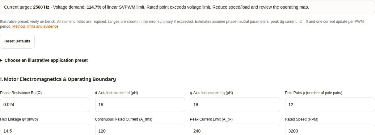
AFPM motor controller tuning calculator software run showing a 2560 Hz current target and 114.7% voltage demand
Original software capture, 2026-11-02: eVTOL synthetic preset, Rs 0.024 Ω, Ld/Lq 18/18 µH, 12 pole pairs, ψf 14.5 mWb, 120 A RMS / 350 A peak, 96 V DC, 6000 RPM, 32 kHz PWM, 200 ns dead time, current bandwidth ratio 0.08, inertia 0.002 kg·m², speed design factor 4, resolver feedback. Load that preset to reproduce the result. Site navigation is outside the capture. This demonstrates software execution, not measured motor performance, customer endorsement or approved hardware gains.

eVTOL / Heavy-Lift Drone Coreless AFPM

Assumptions: 96 V DC, 120 A RMS, 3200 RPM, 12 pole pairs, Ld/Lq = 18/18 µH, Rs = 0.024 Ω, ψf = 14.5 mWb, PWM = 32 kHz.

Calculation: current target 2560 Hz; speed crossover estimate 491 Hz; ripple 41.67 A pp (24.6%); voltage demand 114.7%.

Decision: The rated Id = 0 point exceeds the linear SVPWM voltage limit. Revisit speed/load or the approved operating map before applying gains. Magnet temperature, actual stability and safe weakening speed remain unknown.

EV Traction Dual-Rotor Slotted AFPM

Assumptions: 650 V DC, 280 A RMS, 6500 RPM, 8 pole pairs, Ld/Lq = 82/94 µH, Rs = 0.038 Ω, ψf = 62 mWb, PWM = 20 kHz.

Calculation: current target 1400 Hz; speed crossover estimate 266 Hz; ripple 86.44 A pp (21.8%); voltage demand 108.4%.

Decision: The rated Id = 0 point exceeds the linear SVPWM voltage limit. Revisit speed/load or the approved operating map before applying gains. Magnet temperature, actual stability and safe weakening speed remain unknown.

Precision Robotic Cobot Joint Pancake AFPM

Assumptions: 48 V DC, 25 A RMS, 450 RPM, 20 pole pairs, Ld/Lq = 140/140 µH, Rs = 0.145 Ω, ψf = 22 mWb, PWM = 25 kHz.

Calculation: current target 2250 Hz; speed crossover estimate 352 Hz; ripple 3.43 A pp (9.7%); voltage demand 94.8%.

Decision: The rated Id = 0 point is inside the ideal voltage limit; device drops, transients and bus sag still need margin checks. Magnet temperature, actual stability and safe weakening speed remain unknown.

Industrial Direct-Drive Axial PM Generator/Motor

Assumptions: 380 V DC, 45 A RMS, 900 RPM, 16 pole pairs, Ld/Lq = 420/440 µH, Rs = 0.285 Ω, ψf = 85 mWb, PWM = 16 kHz.

Calculation: current target 960 Hz; speed crossover estimate 218.9 Hz; ripple 13.49 A pp (21.2%); voltage demand 69.4%.

Decision: The rated Id = 0 point is inside the ideal voltage limit; device drops, transients and bus sag still need margin checks. Magnet temperature, actual stability and safe weakening speed remain unknown.

13. Commissioning questions

Inputs and gain conventions

Which resistance and inductance values should I enter?

Use phase-neutral equivalent Rs and differential Ld/Lq for the operating region. Record winding connection, temperature, test frequency, rotor angle and bias current. A line-line reading needs the correct winding conversion; do not paste it as a phase value.

Are current inputs RMS or peak?

Continuous phase current is RMS. The peak limit is phase peak and must be at least √2 times continuous RMS. The amplitude-invariant dq calculations use peak current; a controller with another transform convention needs conversion.

Can I paste these gains directly into an inverter?

Only after checking scaling and algorithm conventions. Kp is V/A and Ki is V/(A·s). Per-unit current/voltage bases, speed units, sample time, anti-windup and vendor register scaling are separate inputs to the implementation.

Does the digital Ki work for both Euler and Tustin?

The displayed Ki/fPWM is for an Euler accumulator with one current update per carrier period. A trapezoidal integrator uses Ki·Ts/2 times the sum of consecutive errors. Incremental PI forms combine proportional and integral coefficients differently.

Current regulation and switching

Why use Kp = L·ωcc and Ki = Rs·ωcc?

For the linear decoupled plant 1/(Ls+Rs), the PI zero cancels the electrical pole, giving a first-order ideal closed current loop. Sampling delay, saturation, parameter drift and imperfect decoupling limit the real bandwidth.

Is the selected current bandwidth proven stable?

No. It is a target. For an ideal cancelled plant with a pure delay of 1.5 PWM periods, phase margin is approximately 90° − 540° times the bandwidth/PWM ratio. At 0.10 this is 36° before other dynamics. Measure actual timing and response.

What does the ripple percentage mean?

The half-duty estimate ΔIpp = Vdc/(4·Lq·fPWM) is divided by √2 times continuous phase RMS current. It is peak-to-peak ripple as a percentage of continuous phase peak, not RMS ripple or a magnet thermal limit.

Should I increase PWM to the suggested minimum?

First check inverter frequency limits, switching loss and thermal headroom. The frequency is calculated for an illustrative 12% ripple target. A designed series choke, a lower bus voltage or another inverter may be more practical; include their losses and integration cost.

What is the dead-time voltage result?

It is the estimated fundamental peak phase-voltage error magnitude (4/π)·tdead·fPWM·Vdc for an idealized current-polarity model. It is not sixth-harmonic voltage amplitude. The duty percentage is time lost relative to one PWM period, not electrical phase lag.

Which signs should decoupling feedforward use?

For the dq equations used here, add vd_ff = −ωe·Lq·iq and vq_ff = +ωe·(Ld·id+ψf) to PI voltage outputs. A different Park transform or summing convention changes signs; verify the firmware equations first.

Position and mechanical response

How does mechanical angle error affect electrical angle?

Electrical angle error is pole pairs times mechanical angle error. At 20 pole pairs, 0.1° mechanical gives 2° electrical. Acceptable error depends on the torque and unintended-Id budget rather than a universal tolerance.

Does every alignment error produce demagnetizing current?

No. The sign of unintended Id depends on offset direction and transform convention. The table reports its absolute magnitude. Its cosine torque approximation excludes reluctance torque, saturation and harmonic flux effects.

How should electrical zero be calibrated?

Follow the motor/inverter alignment procedure using a known stationary stator vector, verified phase sequence, an unloaded guarded shaft and conservative phase-current limits. Validate polarity and sensor direction at low speed before loading. Back-EMF reference angle depends on the transform convention.

How are speed PI gains estimated?

The model uses Kp = J/(a·TΣ·Kt), Ti = a²·TΣ and Ki = Kp/Ti. TΣ is assumed to be 1/ωcc + 2Tpwm, including inner current-loop response and illustrative transport/feedback delay. Actual speed task periods, filtering and resonances can require much slower tuning.

Can a sensorless drive start every AFPM from standstill?

Back-EMF provides no position signal at zero speed. High-frequency injection needs detectable saliency and a validated estimator; near-unity Lq/Ld makes it harder. Assess loaded starts and fault recovery, or use position feedback where required.

Voltage limits, safety and handoff

What does voltage demand above 100% mean?

The selected rated point at Id = 0 requires more fundamental phase voltage than Vdc/√3 in linear SVPWM. Reduce speed or load, review a hardware-rated bus change, or solve an approved field-weakening operating point. Feedforward cannot create extra bus voltage.

Does Ich = ψf/Ld give a safe weakening speed?

No. Ich is the current for complete d-axis flux cancellation in a linear model. It does not determine safe negative Id, loaded speed range or irreversible demagnetization. Partial weakening can still be possible when Ich is above the current limit.

What is a safe magnet temperature?

It is unknown without the magnet grade, temperature-dependent demagnetization curves, geometry and reverse-field operating point. Stator coolant temperature is not rotor magnet temperature. Obtain the manufacturer’s Id-versus-temperature limits and validate rotor heating.

Can this tool select ADC resolution or bearing insulation?

No. ADC selection needs current range, shunt/gain, noise, effective resolution and sampling windows. Bearing-current mitigation needs the actual common-mode circuit, cable and shaft measurements. Inductance alone cannot select either component.

What if motor parameters or JavaScript are unavailable?

Use the static method and commissioning checklist below, collect phase parameters and inverter timing, and request a manual review. Default results are illustrative only. With JavaScript enabled, invalid fields pause results; reset defaults to recover, then copy or download a spec for review.

14. Sources and evidence limits

Published , reviewed by AFPM Motor. Next review due 2027-05-02, or sooner if the model or cited manufacturer guidance changes. Primary technical documentation checked 2026-11-02. General PMSM theory supports the equations; it does not validate an AFPM product or the synthetic presets. Calculation assumptions and illustrative targets are stated separately above.

Imperix TN114 — Motor speed control

Updated 2021-09-22

Outer speed PI design, cascaded torque control and setpoint conditioning.

Limit: Actual inner-loop response, speed sampling, filters and load mechanics still need measurement.

Imperix TN145 — Space Vector Modulation

Published 2021-08-09

Linear modulation range, voltage saturation and integrator management.

Limit: No allowance here for semiconductor drops, DC bus sag or overmodulation.

Microchip — Equation-based Flux Weakening

Online application documentation; checked 2026-11-02

Negative d-axis current and the joint voltage/current constraints.

Limit: Does not provide the magnet-temperature, mechanical-speed or negative-Id limits of your AFPM.

Prepare an inverter matching review

Attach the exported estimate, measured phase parameters, motor temperature conditions, inverter/firmware revision, current and voltage limits, feedback timing, load inertia and required speed/torque map. Use this packet to agree the scope of further engineering support and bench validation.

Inquiry Email

[email protected]

Please include application, peak/continuous torque, speed range, voltage/current limit, outer diameter, axial length, cooling method, quantity, and drawings or reference samples.

Instant Chat

WhatsApp Engineering Support

Share torque-speed, package, cooling, and sample quantity in the first message.