
AFPM Motor Coreless Stator
A coreless AFPM stator carries copper windings without stator iron. Compare torque, gap and cooling with a synthetic example.
Decision summary: compare the architecture, then validate a winding
Reviewed 2026-11-05; next review 2027-05-04. These are design trade-offs, not verified performance promises for a supplied motor. Published by AFPM Motor.
No stator iron means no stator iron-core loss. Other electromagnetic and mechanical losses remain. PCB loss evidence
The winding thickness expands the magnetic gap; consider thicker magnets and rotor mass together. Model assumptions
Low inductance and conductor field exposure make drive and winding selection a joint decision. Manufacturer drive note
1. Calculation method: what is known and what is assumed
This tool estimates sensitivities for a dual-rotor, single-coreless-stator example. It does not size turns, voltage constant, phase resistance or inverter current. The requested shaft power determines required torque; it does not establish that a winding can produce that power.
| Quantity | Method / units | Boundary |
|---|---|---|
| Required torque / electrical frequency | T = P / (2πn/60), f = pn/60; Nm, Hz | Exact kinematics for the entered operating point |
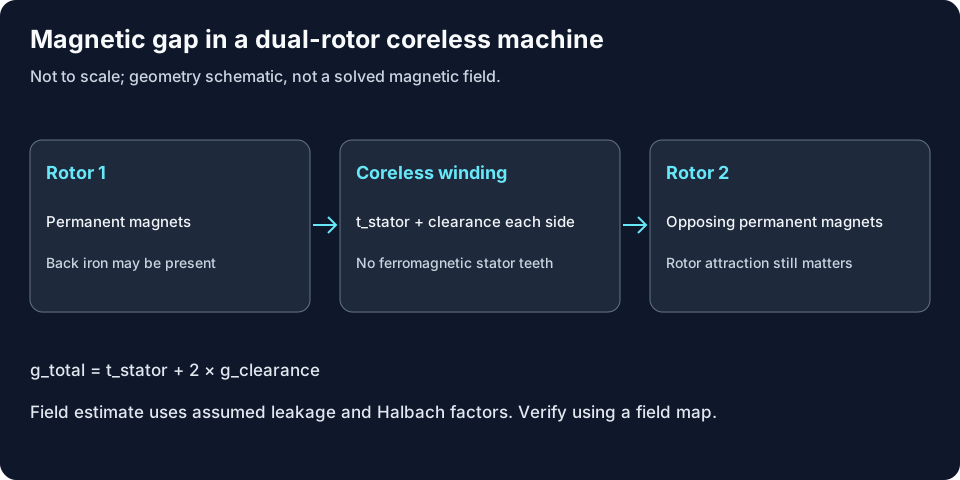
| Magnetic gap | g_total = t_stator + 2g_clearance; mm | Only this double-rotor layout |
| Peak field estimate | Br(T) × 2hm/(2hm + 1.05g_total) × leakage × Halbach factor | Magnet temperature assumed inlet +35°C. Leakage 0.94/0.88, Halbach 1.22, cap 0.92Br are illustrative, uncalibrated |
| Nominal magnet constants (not supplier curves) | Br at 20°C: N42SH 1.32, N45UH 1.36, N38EH 1.25, N52 1.45 T; temperature coefficients −0.0011/−0.0010/−0.00095/−0.0012 per °C | Generic assumed values; no coercivity or demagnetization assessment |
| RMS field / electrical loading | Fundamental of assumed pole coverage 0.88/0.78; loading = T/(2πrm² Δr Brms) | Uniform active radial conductors, ideal winding factor; winding distribution not resolved |
| Copper DC loss | ρ(Tref) × V_copper × J²; W | Tref = inlet + 65°C; end-turn volume = 1.85 × active copper; no thermal feedback |
| Copper / magnet material estimate | 8960 / 7600 kg/m³; assumed pole coverage | Material estimate only, excludes housing and supports |
| Not modeled | Back-EMF, drive compatibility, structural clearance, magnet temperature | Obtain winding geometry, material curves and prototype data |
Reproduce the default screening example
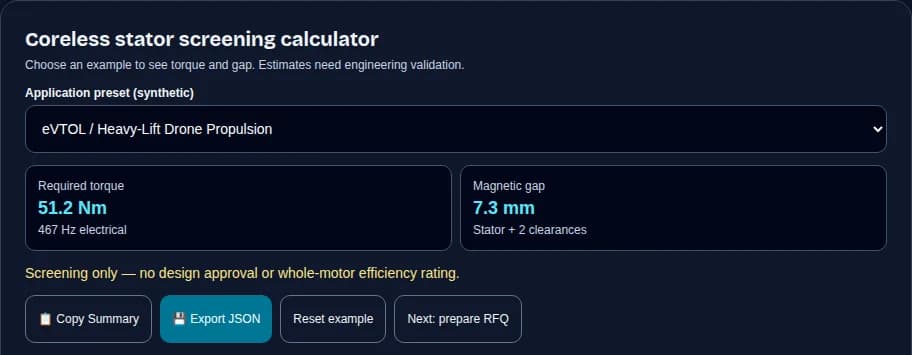
Select the synthetic eVTOL preset: 15 kW at 2,800 rpm, 10 pole pairs, 5.5 mm stator thickness and 0.9 mm clearance on each side. T = 15,000 × 60 / (2π × 2,800) = 51.16 Nm; f = 10 × 2,800 / 60 = 466.67 Hz; total magnetic gap = 5.5 + 2 × 0.9 = 7.3 mm. This checks the software arithmetic only; it is not a tested motor rating.
2. Coreless, slotless and slotted: choose the limiting requirement
Use this qualitative comparison to choose the next engineering investigation. It does not assign universal torque-density, cogging or efficiency percentages; those need equivalent tested machines.
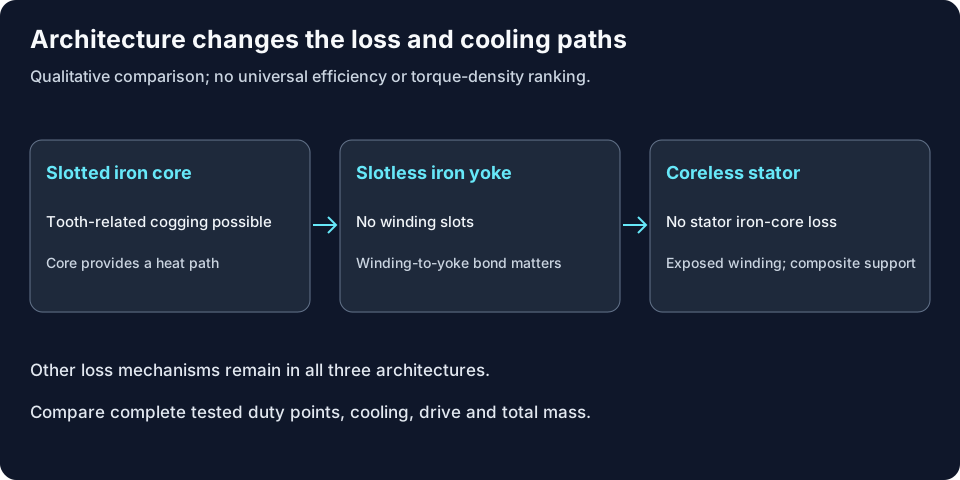
| Requirement | Slotted iron core | Slotless iron yoke | Coreless stator |
|---|---|---|---|
| Tooth-related cogging | Possible; mitigate geometry/control | No slot teeth in active winding | No stator teeth; other ripple remains |
| Stator iron loss | Teeth and yoke may contribute | Yoke may contribute | Zero for a genuinely ironless stator |
| Magnetic gap | Mainly mechanical clearance | Winding adds nonmagnetic thickness | Entire winding disc plus clearances |
| Heat removal | Core may conduct toward housing | Winding-to-yoke interface matters | Composite and cooling boundary dominate |
| Integration cost | Core manufacture and slot winding | Bonding and winding positioning | Self-supporting winding, tooling and encapsulation |
| When to investigate | Volumetric torque priority | Smooth rotation with yoke support | Low detent and low stator iron loss priority |
3. Winding selection: geometry determines the loss model
Round insulated strands, PCB traces and formed foil cannot be compared using a universal loss multiplier. PCB rotor-asymmetry experiments show why trace geometry and interconnects need explicit analysis.
Evidence and scope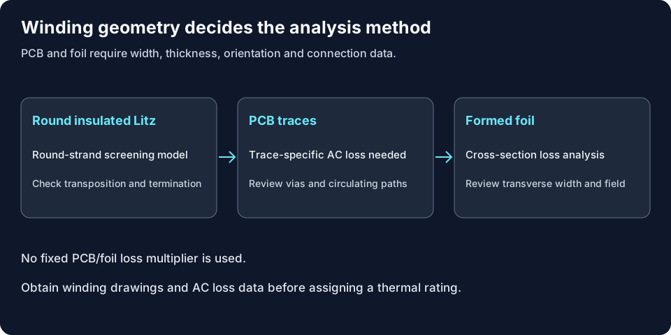
| Option | Potential benefit | Risk / cost | Minimum next step |
|---|---|---|---|
| Potted Litz | Small insulated strands reduce transverse eddy loss | Packing, termination labor and transposition quality | Confirm strand count, insulation, active length and AC resistance |
| PCB | Repeatable etched geometry and integrated traces | Layer yield, vias, circulating paths and cooling | Provide width/thickness/layers and rotor field map for FEA |
| Foil | Formed conductors may improve packing | Field orientation and transverse width can dominate loss | Analyze conductor cross-section and segmentation before procurement |
4. Round-strand eddy loss: fixed-volume scaling, not a universal efficiency curve
The tool uses P_eddy = π² d² B_peak² f² V_active / (8ρ) for a low-frequency sinusoidal transverse field and insulated round strands. At fixed active copper volume, doubling diameter or frequency multiplies this term by four. The d⁴ statement for a single strand of fixed length also changes its copper volume. Skin, proximity, transposition and circulating-current effects require a fuller model.
Evidence and scope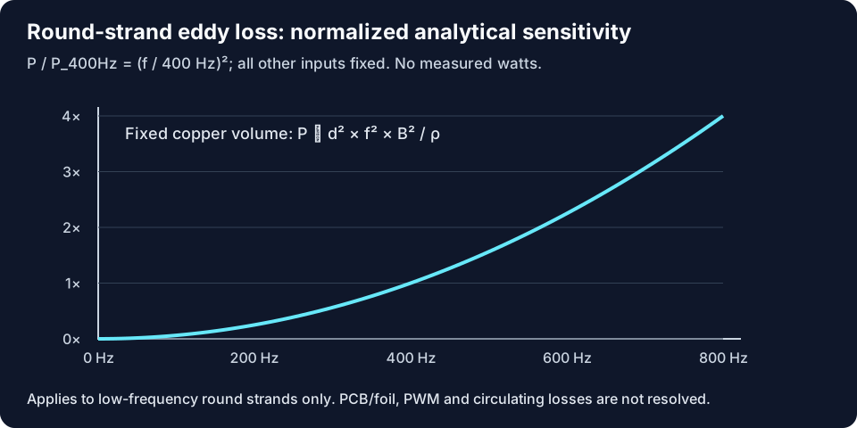
5. Thermal path: both cooled faces are an explicit assumption
The assumed network uses annulus area A: R_resin = t/(4kA), R_fluid = 1/(2hA), T_hotspot = T_inlet + 1.18 × P_modeled × (R_resin + R_fluid). The factor 1.18 and h = 18/65/420/950 W/(m²K) for air/forced air/oil/microchannels are illustrative constants, not validated correlations. An edge-only jacket, a blocked face or partial wetted area invalidates this network. Copper resistivity does not iterate with temperature; large temperature disagreement is explicitly warned.
Evidence and scope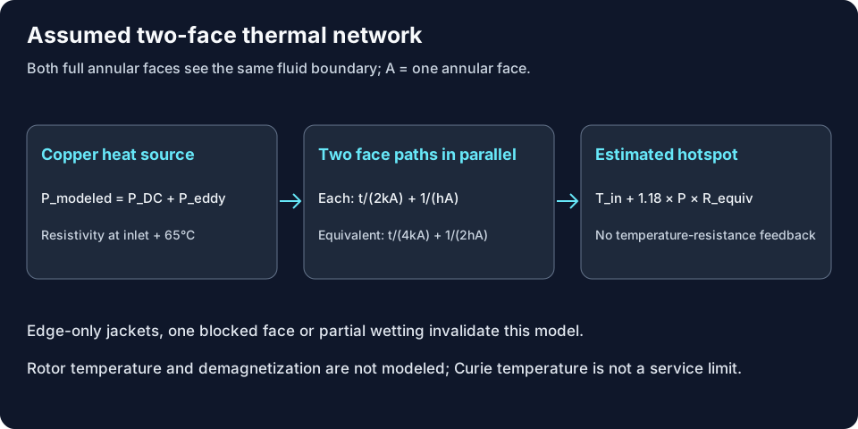
| Unknown | Why it changes the result | How to resolve |
|---|---|---|
| Actual wetted area and h | Sets convection resistance | Measure temperature/flow and calibrate a thermal model |
| Cured composite conductivity | Resin coupons differ from winding assemblies | Use ASTM D5470 apparent conductivity plus assembly tests |
| Resin Tg, adhesive and insulation life | May limit service below the class reference | Obtain cured material curves and thermal-cycle acceptance |
| Rotor temperature and coercivity | Not inferred from stator temperature | Model rotor losses/cooling and check demagnetization curves |
| Copper temperature feedback | Higher resistance can increase loss | Run coupled electrothermal analysis and thermal soak tests |
6. Structural clearance: no automatic deflection verdict
A nonmagnetic stator is not an iron disc subject to rotor-like B²/(2μ₀) attraction. Rotor-to-rotor attraction can still distort rotor supports; the winding reacts Lorentz torque and may see axial loads from local field components. No modulus, boundary condition or measured runout is supplied here, so this calculator does not predict stator deflection or approve clearance.
Evidence and scope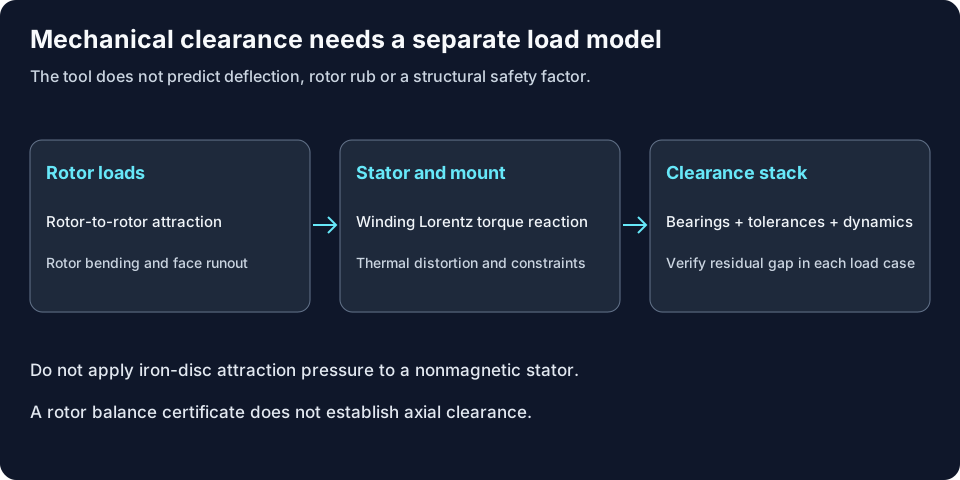
7. Synthetic scenarios: demonstrate a decision, not qualified products
All four presets are illustrative inputs. The table is evaluated from the same model as the tool. A PCB example can provide torque and gap but deliberately has no thermal/efficiency result until trace-specific AC losses are supplied. None of these cases establishes aviation, medical or marine suitability.
| Example and premise | Input / required torque | Model outcome | Next action |
|---|---|---|---|
| eVTOL / Heavy-Lift Drone Propulsion | 15 kW @ 2800 RPM / 51.16 Nm | 103°C assumed face-cooling hotspot; not qualified | Confirm actual cooling and coupled thermal behavior |
| Cobot / Humanoid Robotic Joint | 0.45 kW @ 600 RPM / 7.16 Nm | Thermal result unavailable: trace-specific AC loss missing | Request trace geometry, FEA or measured losses |
| Optical Tracking & Camera Gimbal | 0.15 kW @ 1200 RPM / 1.19 Nm | 59°C assumed face-cooling hotspot; not qualified | Confirm actual cooling and coupled thermal behavior |
| Marine Pod & Industrial Direct-Drive | 45 kW @ 1200 RPM / 358.10 Nm | 66°C assumed face-cooling hotspot; not qualified | Confirm actual cooling and coupled thermal behavior |
8. Published products: keep continuous and peak boundaries separate
The following figures are manufacturer-published, accessed 2026-11-05; they are context, not calibration of our tool or confirmation of current availability. Datasheet maxima may occur at different points. Do not multiply maximum torque by maximum speed to infer a continuous rating.
| Published example | Source values | Recomputed comparison | Boundary |
|---|---|---|---|
| LaunchPoint DHA050 alternator | 1.50 kW continuous, 2.00 kW peak; 0.45 kg; 7000 RPM continuous | 3.33 kW/kg continuous; 4.44 kW/kg peak | PDF table lists 4.4 kW/kg: peak basis |
| LaunchPoint DHA120 alternator | 35 kW continuous, 40 kW peak; 5.78 kg; 6500 RPM continuous | 6.06 kW/kg continuous; 6.92 kW/kg peak | PDF table lists 6.9 kW/kg: peak basis |
| ThinGap TG714X family | 4.26 Nm max continuous torque; 3.57 kW max continuous shaft power; 91% max efficiency | No common-point power density inferred | Family envelope limits; cooling/test point must be checked |
| Infinitum PCB technology | Manufacturer describes PCB stator reliability and copper reduction | No comparable power-density figure established here | Different product/cooling boundaries; no universal PCB rating inferred |
LaunchPoint source PDF · ThinGap source PDF · Infinitum paper
9. Inverter compatibility: use measured inductance and ripple limits
For one illustrative PWM leg model near its worst duty point, ΔI_pp ≈ V_dc/(4 f_sw L). With 800 V and 250 µH, 10 kHz gives about 80 A and 80 kHz gives about 10 A. These are arithmetic examples, not measured coreless-motor data; modulation and line/phase conventions change the coefficient. The calculator does not check drive voltage, current or back-EMF.
Evidence and scope| Question | Evidence to request | Decision |
|---|---|---|
| Is phase inductance compatible? | Measured phase L across current/frequency, bus limits and ripple budget | Choose switching frequency/filter with the drive supplier |
| Can external inductance help? | ThinGap TG714X recommends 70 µH per phase for conventional drives below 40 kHz | Model-family example, not a universal specification |
| Will PWM heat the rotor? | Harmonic loss analysis and rotor thermal measurements | Consider magnet segmentation and modulation |
| Is field weakening adequate? | Ld/Lq, flux linkage and current/voltage envelope | Verify achievable speed before assigning a top-speed rating |
10. Manufacturing route and cost drivers
A practical prototype sequence is: form and electrically inspect the winding; fixture and insulate interconnects; degas and encapsulate using the resin supplier’s process; cure and inspect flatness, voids and insulation. Vacuum level, pressure, cure temperatures and acceptance tolerances must be qualified for that assembly. No generic recipe or lead time is guaranteed.
| Cost risk | Why it matters | Minimum mitigation / alternative |
|---|---|---|
| Custom winding and potting tooling | Geometry changes can consume a second tooling cycle | Freeze interfaces; quote tooling separately from unit price |
| PCB layers, vias and copper weight | Supplier yield can dominate apparent automation savings | Obtain a stack-up DFM review and prototype panels |
| High-frequency drive or filter | Drive loss, size and cost may offset motor mass savings | Compare system bill of materials and measured efficiency |
| Thermal or mechanical rework | A feasible electromagnetic point may fail heat or gap tests | Build a winding coupon and clearance fixture before full motor tooling |
11. Validation plan: failure, evidence and acceptance
Agree the duty cycle and acceptance limits before testing. Catalog standard scopes guide the discussion; this page does not claim compliance with the full standards. For regulated applications, establish the applicable product and system requirements separately.
Evidence and scope| Risk | Evidence / mitigation | Acceptance definition |
|---|---|---|
| Thermal damage or delamination | Thermal soak, thermal cycling and cured resin/adhesive data | Agreed hotspot and bond-life limits, not insulation class alone |
| Rotor-stator contact | Runout, bearing displacement, thermal growth and modal/load tests | Document worst-case residual gap for the actual assembly |
| Converter insulation damage | Actual bus/cable/rise time and IEC 60034-18-41 system qualification | Specify levels with the insulation-system specialist |
| Excess winding/rotor loss | No-load and loaded loss mapping, FEA correlation | Include rotor, PWM/circulating currents and mechanical loss |
| Performance or balance failure | Duty-point dynamometer results; ISO 21940-11 balance report | Separate continuous/peak duration, speed and cooling conditions |
12. Next step: prepare a reviewable RFQ
Export the valid screening inputs and limits, then add the missing winding drawing, bus/current budget, duty profile, cooling contact/flow conditions and rotor clearance stack. For unavailable PCB/foil estimates, request trace-specific FEA or measured losses as the minimum alternative path. Ask for NRE, prototype schedule, validation scope and unit pricing separately.
Explore Adjacent Axial-Flux Engineering Guides
Deepen your powertrain architecture evaluation across related axial-flux design disciplines:
Frequently Asked Questions
Detailed technical responses to core questions regarding AFPM motor coreless stator design, sizing, and validation.
Coreless architecture & magnetic sizing
What is an AFPM motor coreless stator?▼
It is an axial-flux permanent-magnet machine with no ferromagnetic stator teeth or yoke in the active winding. In the double-rotor example used here, axial field crosses a composite-supported winding between two magnet rotors. Rotor back iron may still be present.
Does coreless mean zero torque ripple?▼
Removing stator teeth removes tooth-related cogging in the ideal design. Commutation, current harmonics, bearing friction and manufacturing asymmetry can still produce torque ripple. Validate the assembled drive at the required low-speed operating point.
Why is the magnetic gap larger?▼
The nonmagnetic winding thickness is part of the flux path. For this double-rotor single-stator layout, total gap equals stator thickness plus the two mechanical clearances. Compare magnet mass and clearance together.
Does a Halbach array guarantee 22% more flux?▼
No. The calculator uses 1.22 as an illustrative field factor, with a fixed leakage assumption. Segmentation, magnetization direction, pole pitch and rotor back iron change the actual gain. Use a field map or geometry-specific electromagnetic analysis.
Winding choice & loss interpretation
Why do coreless conductors have eddy losses?▼
Conductors are directly exposed to the rotating main field. Eddy and circulating currents depend on conductor size, connections and local field harmonics. Removing stator iron loss does not eliminate winding or rotor loss; see the PCB loss study below.
Does strand eddy loss scale as d² or d⁴?▼
In the low-frequency round-wire approximation, loss per unit copper volume scales as diameter squared at fixed field and frequency. Loss for one strand of fixed length scales as diameter to the fourth because its volume also increases with diameter squared.
When is the round-strand calculation unavailable?▼
PCB and foil need conductor width, thickness, orientation and interconnection data; this tool does not infer those losses. It also withholds the strand estimate above one-third skin depth as a conservative modeling boundary. The boundary is not a wire selection standard.
Is a PCB stator always suitable only below 3 kW?▼
No universal power cutoff is supported here. Layer stack, trace geometry, thermal interfaces, cooling and manufacturing constraints determine the rating. Request a drawing-specific loss and thermal model instead of applying a generic power threshold.
Thermal assumptions & materials
Which heat path does this calculator use?▼
It assumes equal heat removal through both full annular faces to fluid at the selected inlet temperature and heat-transfer coefficient. A peripheral water jacket or a plate cooling only one face does not satisfy this boundary.
Is positive thermal class difference a pass?▼
No. It is a subtraction from a class reference only. Resin glass-transition temperature, adhesive strength, insulation aging and the actual duty cycle can impose lower limits. Prototype temperature measurements remain necessary.
Why is copper resistivity fixed at inlet plus 65°C?▼
That is a disclosed reference-temperature assumption to keep this screening model deterministic. It does not solve temperature-resistance feedback. Large differences from the estimated hotspot trigger a warning and require coupled electrothermal analysis.
Can this tool predict magnet demagnetization?▼
No. It lacks rotor losses, rotor cooling and the operating point on temperature-dependent demagnetization curves. Magnet grade suffixes or a nominal maximum temperature cannot establish a demagnetization margin.
Clearance & structural verification
Does the ironless stator experience rotor-like magnetic attraction?▼
A nonferromagnetic stator cannot be treated as an iron disc carrying magnetic pressure B²/(2μ₀). Rotor-to-rotor attraction still matters. Winding Lorentz loads, mount constraints, thermal distortion and vibration need separate structural evaluation.
How should rotor-stator clearance be verified?▼
Combine rotor face runout, bearing displacement, assembly tolerances, thermal growth and dynamic deformation in a documented stack. Agree a minimum residual gap for each load case and confirm it on a prototype; this calculator gives no clearance approval.
Does rotor balance guarantee axial flatness?▼
No. ISO 21940-11 concerns rotor balance. Face runout, bearing play, rotor bending and stator mounting distortion require separate measurement. A good balance certificate cannot replace an axial clearance stack.
Should conductive reinforcement be placed in the active gap?▼
Conductive reinforcement may add eddy-loss paths. Evaluate electromagnetic heating, insulation and structural compatibility before choosing it. Glass-fiber or other nonconductive supports may be candidates, subject to material and thermal testing.
Drive compatibility & procurement
Does every coreless motor require SiC or GaN?▼
No. Select the drive using measured phase inductance, bus voltage, current ripple and loss limits. ThinGap gives a model-family example with external inductance for conventional drives below 40 kHz; that is not a universal rule for AFPM machines.
Is the displayed efficiency a motor efficiency rating?▼
No. It includes only the modeled DC and round-strand eddy loss. Rotor eddy loss, PWM and circulating currents, bearings, windage, inverter losses and cooling power are excluded. Whole-system efficiency requires a measured power balance.
What should an OEM RFQ include?▼
Provide continuous and peak torque/speed with duration, bus and phase-current limits, envelope, cooling boundary, operating environment, clearance constraints and acceptance tests. Attach the screening export with its assumptions and identify missing winding or thermal data.
What prototype lead time should I assume?▼
No verified lead-time promise is provided on this page. Ask the supplier to confirm winding or PCB capacity, tooling, resin availability, test fixtures and first-article acceptance before agreeing a schedule or cost.
Primary Standards & Engineering Literature References
Direct source records checked 2026-11-05. Manufacturer statements are identified as such; catalog summaries do not replace full standard clauses. Model coefficients without validation are disclosed as assumptions.
[1] Wang & Kamper — Calculation of Eddy Current Loss in Axial Field PM Machine With Coreless Stator
[2] Chulaee et al. — Circulating and Eddy Current Losses in Coreless Axial Flux PM Machine Stators with PCB Windings
[3] LaunchPoint EPS — Electric Machines & Controllers data sheet
[4] ThinGap — TG714X permanent magnet machine data sheet
[5] Infinitum — Designing Electric Motors for Intrinsic Reliability
[6] IEC 60034-1:2026 — Rating and performance
[7] IEC 60085:2007 — Electrical insulation: Thermal evaluation and designation
[8] IEC 60034-18-41:2014+AMD1:2019 — Type I converter-fed insulation systems
[9] ASTM D5470 — Thermal transmission properties of insulating materials
[10] ISO 21940-11:2016 — Rotor balancing with rigid behaviour
Request Custom Coreless Stator Sizing or Prototype Quotation
Ready to evaluate a custom ironless axial-flux architecture for your drone, robotics, or high-efficiency direct-drive system? Submit your mechanical envelope and performance targets for DFM review and prototype lead time analysis.
Inquiry Email
Please include application, peak/continuous torque, speed range, voltage/current limit, outer diameter, axial length, cooling method, quantity, and drawings or reference samples.
Instant Chat
WhatsApp Engineering Support
Share torque-speed, package, cooling, and sample quantity in the first message.