
AFPM Motor Cooling Design
Thermal resistance sizing, potting conduction, dielectric fluid selection, and rotor-stator gap drag estimates.
Uncalibrated estimate; laminar oil-drag reference. No S1 verification. Assumptions & limits
AFPM Thermal & Fluid Calculator
All inputs are required. Power 0.1–2500 kW; EM efficiency 60–99.9%; loss fractions 0.01–0.99 each, sum < 1; flow 0.1–5000 L/min; inlet −40–120°C; ambient −40–85°C; outer diameter 50–1500 mm; inner diameter ≥20 mm and below outer; stack 5–300 mm; gap 0.2–10 mm; speed 1–30000 RPM; conductivity 0.1–10 W/m·K; path 0.1–50 mm. Fluid properties are fixed near 40–70°C; other temperatures are extrapolations.
1. Operating Load & Losses
2. Cooling Circuit & Coolant
3. Geometry, Speed & Potting
Environment & axial geometry
4. Limits & Material Ratings
Model indicates temperature headroom
Model indicates temperature headroom under the stated assumptions. This does not verify an S1 rating.
Next: plan measurements and prototype validation, or export these inputs and estimates for engineering review. No measured accuracy is established. Channel geometry, fin area, oil coverage and hotspot allowances are assumed; see method and limits.
Stator Thermal Gradient & Resistance Stack
Total R_th = 0.012 K/WHydraulic Circuit Dynamics
Air-Gap Drag & Churning
Engineering Recommendations & Boundary Warnings
- •Next: obtain measured losses, fluid properties and pressure-flow data, then validate the candidate on a dynamometer.
Plan Your Thermal Design Review
Submit your torque-speed duty cycle, packaging volume, and cooling loop limits to scope simulation and prototype validation.
Inquiry Email
Please include application, peak/continuous torque, speed range, voltage/current limit, outer diameter, axial length, cooling method, quantity, and drawings or reference samples.
Instant Chat
WhatsApp Engineering Support
Share torque-speed, package, cooling, and sample quantity in the first message.
Published by AFPM Motor. Model calculations are reproducible software examples; no hardware test results are claimed.
1. Cooling decisions to make first
For AFPM motor cooling design, start with the loss map and heat path, then compare the complete cooling circuit. A topology name alone cannot establish continuous power, cost or reliability. This guide separates published evidence, explicit model assumptions and measurements still needed.
| Decision | Evidence or method | Next action |
|---|---|---|
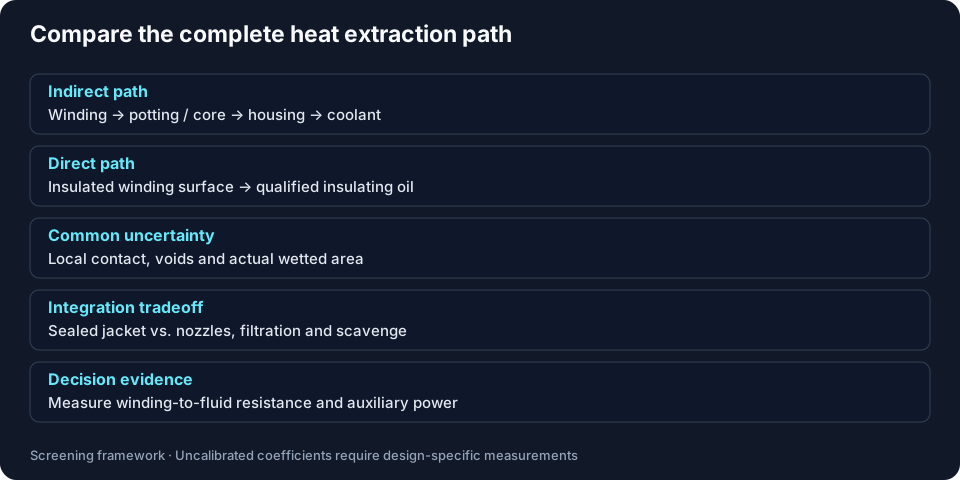
| Shorten the dominant heat path before adding flow | Integrated-channel design study [1] | Measure winding-to-coolant resistance. |
| Keep oil inventory and drag in the comparison | Design-specific direct cooling study [2] | Measure no-load torque with the intended oil level. |
| Separate circuit classification from performance approval | IEC cooling classification [3] | Request a complete circuit drawing and qualification data. |
| Set fluid limits for the selected system | Particle coding method [4] | Agree supplier limits; do not infer them from a test-method number. |
2. Find the AFPM thermal bottleneck
A dual-rotor machine can place the stator between two moving surfaces. Heat may need to travel through encapsulation, teeth and housing contacts before reaching a peripheral jacket. A single-rotor arrangement or a purpose-built cooling plate has different paths. This calculator represents a dual-face annular stator; compare another architecture with its own geometry.
The 2024 integrated-channel study [1] evaluates a particular SMC stator geometry. It supports investigating shorter paths, while its coefficients and results remain specific to that design.
3. Five cooling topologies and their tradeoffs
| Topology | Heat path | Cost and integration burden | Failure mode / mitigation |
|---|---|---|---|
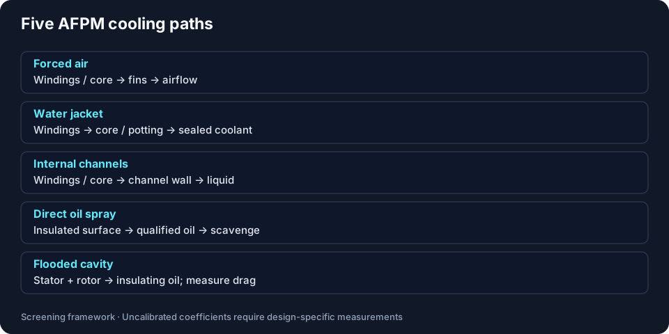
| Forced air | Winding/core → fins or ventilated faces → air | Fan or propwash, ducts and acoustic budget | Blocked ducts or low hover airflow; validate fan and duct curves. |
| Peripheral water jacket | Winding → core/potting → housing → sealed coolant | Often fits an existing vehicle loop; contact quality matters | Potting/contact bottleneck; measure thermal resistance before increasing flow. |
| In-slot / tooth channels | Winding/core → wall → contained liquid | More complex core, channel and leak inspection | Local leakage or flow imbalance; pressure-test and balance branches. |
| Direct oil spray | Insulated winding surface → qualified oil | Nozzles, filtration, scavenge and fluid qualification | Dry spots or pooled oil; check coverage and retained volume across orientation. |
| Flooded oil cavity | Winding and rotor surfaces → qualified oil | Sealing, oil inventory and drag budget | Viscous heat and seal loading; measure drag over speed and viscosity. |
IEC 60034-6:1991 [3] classifies circuits and coolant movement. Assign the full IC designation from the actual circuit with the supplier. Direct spray is not automatically an IC 91W/97W design, and an IC code does not establish IP protection.
4. Calculator method, assumptions and limits
This is an uncalibrated steady-state sensitivity model. It cannot verify an S1 rating, demagnetization safety, fluid compatibility or transient duty. The synthetic presets illustrate model behavior and carry no measured accuracy claim.
| Quantity | Calculation / assumption | What must be supplied for a real design |
|---|---|---|
| Electromagnetic loss | P_loss = P_shaft × (1/η_EM − 1); copper and iron fractions, remainder assigned to rotor | Measured loss map; separate windage already included in efficiency. |
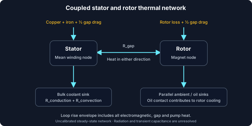
| Loop heat envelope | Q_loop = P_loss + P_gap + P_pump; ΔT = Q_loop/(ρ × volume flow × cp) | Actual split to ambient and external-loop losses. This envelope is not a measured outlet temperature. |
| Conduction | R = 0.5 × path/(k_effective × area); jacket uses 4.5× resin conductivity and 1.5× perimeter area | These multipliers represent assumed parallel paths and are not calibrated core properties. |
| Convection | R = 1/(h × wetted area); air area 3.2×, spray area 2.8× annular face; spray h = min(4500, 650 × nozzle velocity^0.6) W/m²K; no fixed low-flow floor | Measured fin efficiency, nozzle coverage and heat-transfer curves. |
| Stator and rotor | Simultaneous two-node heat balance; gap drag split equally; spray oil contact also cools the rotor in parallel with ambient; hotspot adds 14% of positive winding-to-bulk rise | Contact resistance, radiation, directional core conduction and local hotspots are unresolved. |
| Hydraulics | Assumed lengths: jacket 3 circumferences, internal channels 2 radial passes, eight 3 mm nozzles of length 20 mm, flooded path one radial span; Darcy–Weisbach estimate, pump efficiency 65% | Real channel lengths, roughness, fittings, pump and scavenge curves. |
| Fluid properties | Fixed illustrative values near 40–70°C; no phase-change or viscosity-temperature model | Product-specific data across operating temperature and aging. Outside this band, treat results as extrapolation. |
| Screening margins | Nominal insulation and magnet limits minus estimated temperatures; caution buffers and the 5% auxiliary-power flag are tool assumptions | System qualification and supplier magnet B-H curves at current and temperature. |
Channel convection uses a simplified laminar/turbulent correlation with a transition at Re = 2300. The transition region and nozzle correlations are not validated here. If a calculated outlet exceeds the fluid property range, reduce load or use a property-dependent model before making a selection.
5. Four reproducible screening examples
These are synthetic inputs, not OEM specifications or dynamometer benchmarks. Select the matching preset in the tool, change one assumption, and export both results for comparison. The same domain engine generates this table and the interactive outputs.

| Preset | Power / speed | Flow / inlet | Winding hotspot | Rotor magnet | Gap drag | Required follow-up |
|---|---|---|---|---|---|---|
| 60 kW Commercial EV Traction | 60 kW / 3600 RPM | 12 L/min / 65°C | 107.2°C | 108.6°C | 8 W | Measure heat path and actual flow distribution. |
| 180 kW High-Density eVTOL / Hypercar | 180 kW / 6000 RPM | 16 L/min / 60°C | 141.7°C | 115.0°C | 210 W | Measure heat path and actual flow distribution. |
| 12 kW Lightweight Drone / UAV Propulsion | 12 kW / 2800 RPM | 4500 L/min / 30°C | 136.8°C | 105.2°C | 0 W | Measure duct and propwash performance. |
| 250 kW High-Torque Marine Direct-Drive | 250 kW / 1200 RPM | 28 L/min / 45°C | 144.4°C | 59.7°C | 293 W | Measure drag and oil temperature over speed. |
Published comparison data for a common test protocol, coolant inlet, duty and winding definition are insufficient here to rank YASA, Magnax/Traxial or other commercial platforms. Request their dated supplier datasheets and test conditions instead of comparing an inferred continuous-to-peak ratio.
Export your inputs and screening results before requesting a thermal design review.
Compare your cooling inputs6. Potting, contact resistance and thermal cycling
Higher bulk resin conductivity only helps when voids, bondline thickness and housing contact are controlled. For equal geometry, doubling conductivity halves the resin contribution to thermal resistance; it does not halve total winding temperature rise.
| Interface | Known design dependency | Required supplier or process evidence |
|---|---|---|
| Copper / enamel / potting | Thermal expansion mismatch can strain the bond | Cured CTE, modulus and adhesion versus temperature; representative thermal-cycle results. |
| Core / resin | Directional core conduction and local voids affect the heat path | Measured effective conductivity, sectioned samples and void inspection. |
| Potting / housing | Bondline and pressure govern contact resistance | Thickness tolerance, surface preparation and measured joint resistance. |
| Glass transition | Modulus and expansion change across Tg | DMA/DSC data and qualified operating range; Tg alone is not a life rating. |
Free mismatch strain can be screened as Δε = Δα × ΔT. Multiplying this by a modulus is not a general interfacial shear solution: constraint, geometry and viscoelastic relaxation matter. Cycle a representative assembly and remeasure thermal resistance and electrical integrity before selecting a resin.
7. Direct oil cooling and rotor-stator drag
Axial rotor-stator disc flow differs from cylindrical Taylor-Couette flow. For two smooth annular faces in narrow-gap laminar shear, P_gap = π × μ × ω² × (Ro⁴ − Ri⁴)/gap. Turbulent disc estimates often use a coefficient multiplying ρ × ω³ × radius⁵; that coefficient changes with regime and geometry, so cubic speed scaling is not universal.
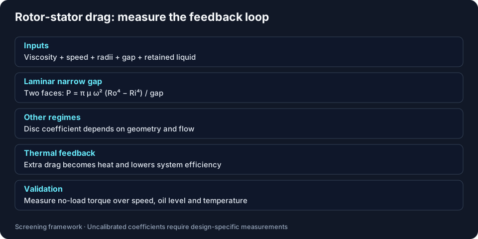
The tool reports only the analytical laminar smooth-disc shear reference. Turbulent and multiphase drag are unresolved; the reference must not be treated as a prediction at arbitrary speed. Spray combines assumed 4% oil coverage with 96% dry windage; the same wet fraction contributes to rotor cooling. This is a sensitivity assumption requiring measured validation. Measure no-load torque, retained oil, viscosity and scavenge performance to replace those assumptions. The SAE design study [2] illustrates why conclusions must remain geometry-specific.
8. Rotor temperature and demagnetization limits
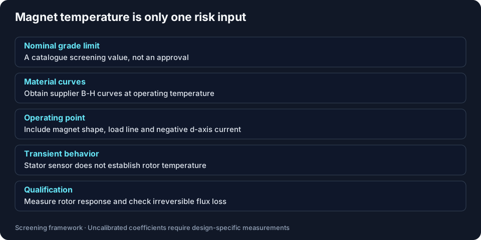
The tool compares estimated temperature with nominal catalogue-style limits: N52 80°C, SH 150°C, UH 180°C and EH 200°C. These are screening assumptions, not universal irreversible-loss thresholds. Obtain the actual material curves, permeance coefficient and worst demagnetizing current from the motor supplier.
Stator and rotor responses can differ during repeated launches. Neither thermal capacitance nor a transient observer is included here; no generic 15–40 s or 150–300 s time constant is established. Instrument the rotor or validate an observer before allowing repeated burst or field-weakening operation.
9. Dielectric fluid qualification and service limits
| Question | Evidence / method | Acceptance decision |
|---|---|---|
| Are particles controlled? | ISO 4406 coding [4] | Supplier-agreed code based on nozzle, bearing and insulation testing; no universal 16/14/11 requirement. |
| Is water content controlled? | ASTM D1533 water measurement [8] | Fluid-specific water content and saturation limits; no universal 50 ppm rejection level. |
| Are materials compatible? | ASTM D3455 scope [5] | Agree an adaptation for synthetic fluid; test exact enamel, resin, seals and additives. |
| Is the electrical system qualified? | IEC 60034-18-41 [7] | Representative winding/inverter tests; D149 solid tests [6] do not certify liquid breakdown. |
| Are aeration and aging acceptable? | Application-specific air release, acidity and heat-transfer tests | Set baseline and service limits with suppliers; no universal void fraction or change interval. |
Sharing a gearbox sump can reduce plumbing but introduces wear debris and additive compatibility questions. Specify sampling locations, filtration, pressure bypass behavior and fluid change criteria, then test the complete shared circuit.
10. Hydraulic and manufacturing constraints
The pressure-drop result covers the assumed internal geometry only. Add hoses, filter fouling, heat exchanger, fittings and scavenge equipment before choosing a pump. A 120 kPa restriction at 15 L/min requires 30 W hydraulic power or 46.2 W input at 65% efficiency; those numbers follow directly from Δp × volume flow.
| Risk | Evidence to obtain | Mitigation / alternative |
|---|---|---|
| Restriction and parasitic power | Hot/cold pressure-flow curves and worst-case filter loading | Larger passages or parallel branches; evaluate pumping and flow balance together. |
| Seals and oil retention | Leakage and retained-volume tests over orientation and speed | Scavenge and vent redesign; compare a sealed jacket if open oil is unsuitable. |
| Channel manufacturing yield | Inspection access, wall thickness, proof-pressure and leak results | Prototype a simpler jacket before committing to integrated channels. |
| False savings from better resin alone | Total thermal-resistance breakdown and process yield | Control bondline and voids; compare changed geometry against material cost. |
11. From a screen to a qualified continuous rating
| Stage | Measure | Decision / limitation |
|---|---|---|
| Loss mapping | Torque, speed and electrical power with stated uncertainty | Separate electromagnetic, mechanical and auxiliary losses. |
| Steady-state thermal run | Embedded winding/core sensors, rotor measurement or validated observer, coolant temperatures and flow | Demonstrate equilibrium and agreed temperature limits across the declared operating envelope. No universal three-hour rule is asserted here. |
| Repeated duty | The real torque-speed-time sequence and initial temperatures | Correlate a transient model; the steady-state calculator cannot approve bursts. |
| Electrical and fluid aging | Representative samples before/after fluid exposure and thermal cycling | Agree test voltages, PD criteria and compatibility limits with qualified test personnel. |
| Production control | Leak testing, potting inspection and thermal resistance sampling | Carry prototype assumptions into documented process controls and traceability. |
12. Choose the next measurement before the next topology
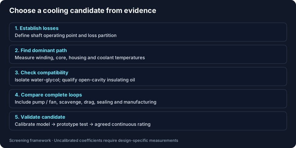
If the loss map or thermal resistance is unknown, export the synthetic screen as a hypothesis and request those measurements. If the model flags low margin, reduce load and investigate the dominant resistance. If it shows headroom, progress to a calibrated model and prototype test; the result still does not approve a motor rating.
Frequently asked engineering questions
Architecture and operating point
Why can a dual-rotor AFPM stator be difficult to cool?
Rotors occupy both axial faces, which can lengthen the path from windings to a peripheral jacket. The severity depends on the stator core, copper, encapsulation and housing contacts. Other AFPM layouts can expose an axial face for a cooling plate.
When should I start with a peripheral water jacket?
Start there when a sealed circuit and existing vehicle coolant loop simplify integration. Measure the coil-to-housing thermal resistance before increasing pump flow; a conduction bottleneck may dominate.
Is there a universal current-density limit for direct oil spray?
No. Winding geometry, wetting, fluid temperature, electrical insulation and duty cycle all matter. This tool does not calculate current density or certify continuous power.
Can I compare forced air with liquid cooling?
Yes, as an initial sensitivity study. Air uses a much higher volumetric flow and assumed fin area. A fan curve, duct restriction and measured heat-transfer data are needed to compare real systems.
Calculator inputs and uncertainty
Are the four presets production motor specifications?
No. They are synthetic worked examples for different cooling paths. Their temperatures are model outputs, with no measured accuracy or S1 rating attached.
Which efficiency should I enter?
Enter electromagnetic efficiency at the chosen shaft power and speed, excluding the additional gap-drag and external pump terms calculated here. A measured overall motor efficiency may already include windage; separate those losses before using it to avoid counting them twice.
What happens to losses not assigned to copper or iron?
The remainder is assigned to rotor heating for this simplified model. Replace this partition with measured or electromagnetic-analysis losses when assessing an actual design.
Why can water-glycol not be selected for a flooded cavity?
The tool assumes exposed winding and rotor surfaces for spray and immersion. Water-glycol must be isolated in sealed passages. A specially qualified canned design requires a separate model.
Fluid mechanics and materials
Is axial disc drag the same as cylindrical Taylor-Couette flow?
No. An axial rotor-stator cavity has different geometry and boundary conditions. The tool uses an annular shear estimate with an illustrative turbulent allowance; it does not predict Taylor-Couette transition thresholds.
Does dry-sump spray eliminate rotor drag?
No. Scavenging can reduce retained oil, but wetting, mist, pooling and windage remain. The tool assumes 4% liquid coverage as a sensitivity parameter, not a measured guarantee.
Can standard ATF replace a dielectric PAO fluid?
Only after qualifying the exact formulation with enamel, resin, seals and electrical stress. Chemistry and viscosity differ by product; generic fluid names do not establish compatibility.
How is pumping power calculated?
Pump input power is pressure drop times volume flow divided by assumed efficiency. At 120 kPa, 15 L/min and 65% efficiency, the result is 46.2 W. Scavenge pumps, fans and the external heat exchanger are additional system loads.
Thermal limits and validation
Does a positive margin verify an S1 rating?
No. It compares a screening temperature with a nominal material limit. Confirm thermal equilibrium, insulation-system limits and the full duty cycle on an instrumented prototype.
Can the calculator approve repeated launches?
No. It is steady state and has no thermal capacitances or transient loss map. Measure rotor and winding responses and validate a transient model for repeated bursts.
Are magnet grade temperatures demagnetization thresholds?
No. They are nominal catalogue screening limits. Irreversible loss depends on the supplier B-H curves, magnet shape, load line and demagnetizing current at temperature.
Does more flow always solve a winding hotspot?
No. Flow may reduce coolant rise while barely changing a dominant resin or contact resistance. Compare the resistance breakdown and measure winding-to-housing temperature differences.
Procurement and service decisions
Does an IEC cooling code establish an IP rating?
No. Ask for the circuit designation and the separate enclosure protection specification with its test evidence. Do not infer either from a topology name.
Does ISO 4406 require a 16/14/11 oil cleanliness target?
No. It supplies a contamination code. Agree the actual cleanliness target with the motor, fluid, bearing and nozzle suppliers and validate it with samples.
How should I specify resin thermal-cycle reliability?
Request cured conductivity, CTE, modulus and glass-transition data over the intended temperature range. Cycle representative potted assemblies and remeasure thermal resistance and electrical integrity.
What should I send for a thermal design review?
Send the torque-speed-time duty cycle, measured loss map, package geometry, fluid data, inlet temperature and pressure-flow limits, insulation details, magnet curves and acceptance criteria. Export this screening result with its assumptions as supporting context.
Primary references, scope and evidence gaps
Sources checked 2026-11-05; next planned review 2027-05-04. Publisher abstracts and catalogue descriptions establish the scope stated below. Full standards and design-specific test records must be consulted for qualification. None of these sources validates the calculator multipliers or supplies the missing OEM comparison data.
[1] A Novel Cooling System for High-Speed Axial-Flux Machines Using Soft Magnetic Composites
Energies 17(22), 5615 (2024)
Supports: A specific integrated stator-channel design is studied using design-specific thermal and fluid simulation.
Limit: Its geometry-specific findings do not calibrate this calculator or set universal current-density limits.
[2] Axial Flux Motor Design Solutions for Loss Reduction, Cooling Enhancement, and Manufacturability Improvement
SAE 2026-01-5001 (2026)
Supports: The public abstract discusses stator cooling and direct air-gap oil cooling in a particular motor design.
Limit: An individual design does not establish a universal speed cutoff or validate the tool coefficients.
[3] IEC 60034-6:1991 — Methods of cooling (IC Code)
Edition 2.0 (1991)
Supports: Classifies cooling circuit arrangements and coolant movement methods.
Limit: Ask the supplier to assign the full designation from its circuit drawing. An IC designation does not certify IP protection or thermal performance.
[4] ISO 4406:2021 — Coding solid particle contamination
Edition 4 (2021)
Supports: Defines a coding method for solid particle quantities in hydraulic fluids.
Limit: It does not prescribe an AFPM cleanliness acceptance limit or measure water content.
[5] ASTM D3455-11 — Construction material compatibility with petroleum-origin insulating oil
Publisher catalogue checked 2026-11-05
Supports: Provides a compatibility test framework for construction materials and petroleum-origin insulating oil.
Limit: Synthetic PAO and ATF require an agreed, fluid-specific adaptation; the catalogue is not an AFPM material approval.
[6] ASTM D149-20 — Dielectric strength of solid insulating materials
2020 edition
Supports: Addresses solid insulation testing at commercial power frequencies.
Limit: It is not a liquid breakdown test, a universal kV/mm threshold, or inverter pulse qualification.
[7] IEC 60034-18-41:2014+AMD1:2019 — Type I converter-fed insulation systems
Consolidated edition 1.1 (2019)
Supports: Covers qualification and quality-control assessment of converter-fed winding insulation systems.
Limit: It does not supply a universal multiple of bus voltage for every motor, cable and inverter configuration.
[8] ASTM D1533-20 — Water in insulating liquids by coulometric Karl Fischer titration
2020 edition
Supports: Measures water content in insulating liquids.
Limit: Water acceptance and service limits must come from the selected fluid and insulation qualification.
Related Axial Flux Engineering Guides & Sizing Tools
Explore adjacent electro-mechanical design aspects of high-performance axial flux machines:
Ready to Validate Your AFPM Thermal Architecture?
Share your duty cycle, loss map, package and coolant limits to scope a thermal design review and agree the required simulation and prototype test work.
Inquiry Email
Please include application, peak/continuous torque, speed range, voltage/current limit, outer diameter, axial length, cooling method, quantity, and drawings or reference samples.
Instant Chat
WhatsApp Engineering Support
Share torque-speed, package, cooling, and sample quantity in the first message.