
AFPM Motor Custom Design
Compare torque, geometry, voltage and cooling assumptions. Start with a preset, then export a concept brief.
Decisions to make before a custom motor order
Define the constraint
Optimize diameter ratio only after defining what stays fixed.
Compare at the same operating point
Use phase RMS consistently; recheck winding, current and bus limits together.
Validate continuous capability
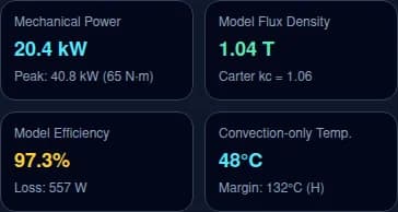
Assumed convection and a positive thermal margin do not establish a rating.
Scope the validation plan
Resolve local disc force, net bearing thrust, test scope and project costs.
Model method, known inputs and unknowns
Synthetic screening model, not a validated motor design or FEA solver input. Balanced sinusoidal three-phase star connection; current and phase voltage use RMS. Fixed winding factor 0.945, nominal magnet properties, heuristic losses/mass/inductance, 40°C sink, assumed h and convection-only thermal resistance. Omits internal thermal paths, saturation, PWM, coolant flow, magnet temperature and peak duration. Compare concepts; verify with winding layout, FEA and tests before selecting hardware.
Known: the operating targets and envelope you enter. Derived: power, speed, frequency and annular geometry. Assumed: pole coverage, winding factor, turns target, slot geometry, conductor fill, inductance, losses and mass. Unknown: measured winding and core data, torque capability, coolant circuit, internal thermal paths, peak duration and structural qualification. Same inputs give the same outputs; no experimental accuracy band is available.
The loss model uses generic frequency-dependent coefficients, not a fitted material loss map. The 40°C sink and all cooling coefficients are fixed comparison assumptions. Peak power is requested torque × speed × multiplier, not a feasible operating envelope. Exported JSON is a brief for an engineer, not a solver-ready mesh or configuration.
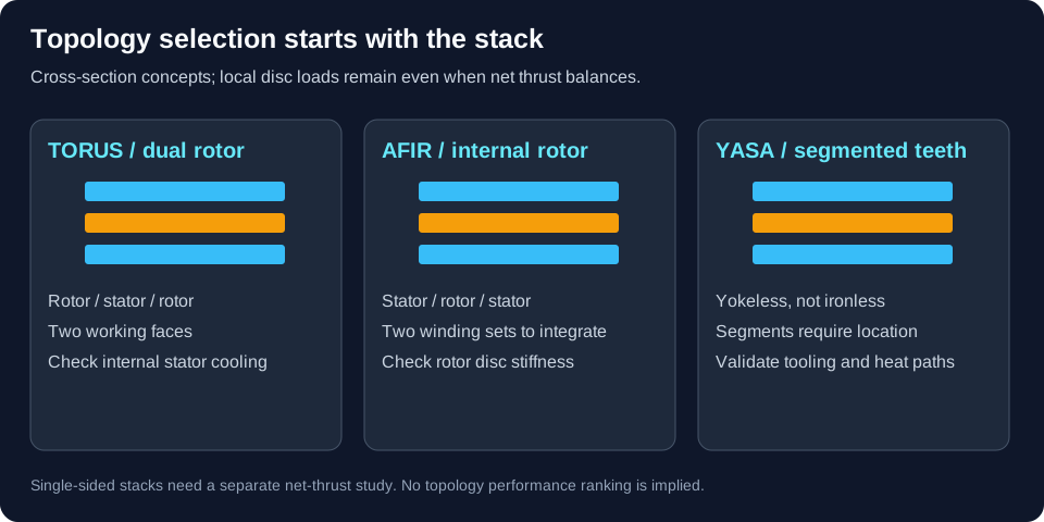
1. Choose a topology by the integration constraint
Start with the mechanical stack and the cooling interface. A topology name alone cannot determine power density or efficiency. The calculator only distinguishes one versus two active faces; TORUS, AFIR and YASA comparisons require geometry-specific models.
Source and scope: Gieras, Wang & Kamper — Axial Flux Permanent Magnet Brushless Machines
| Architecture | Potential benefit | Design check / alternative |
|---|---|---|
| TORUS-NS / dual rotor | Internal stator with two working faces | Check rotor disc bending and stator heat extraction. |
| TORUS-NN | Alternative return-flux path | Provide the ferromagnetic return path; do not pair with an ironless stator. |
| AFIR | External stators can connect to the housing | Check two winding sets, terminations and internal rotor stiffness. |
| YASA | Segmented teeth without continuous stator yoke | Price tooth tooling, segment location and cooling seals; it is not ironless. |
| Single rotor / single stator | Simple stack worth comparing at small axial length | Resolve net axial thrust and housing stiffness. |
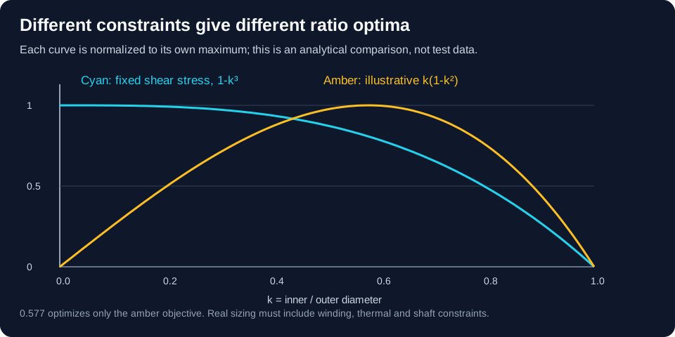
2. Diameter ratio: state the objective before optimizing
Our derivation: for fixed outer radius and uniform shear stress τ, integrate dT = 2π τ r²dr to obtain T = (2π τ/3)(Ro³-Ri³) per face. Therefore T scales with 1-k³ for k=Ri/Ro. The separate illustrative function k(1-k²) peaks at 1/√3≈0.577 only when its loading constraint applies. It cannot be obtained by merely rearranging (Do²-Di²)Dm. This tool uses your ratio and does not optimize it.
| Quantity | Expression / convention | Decision boundary |
|---|---|---|
| Inner diameter | Di = k Do | Shaft, seal and cable pass-through constrain the minimum. |
| Mechanical power | P = T × 2πn/60 | A requested operating point, not verified motor capacity. |
| Electrical frequency | fe = p n/60; p = pole pairs | Conductor AC losses and control bandwidth depend on frequency. |
| Rotor tip speed | v = π Do n/60 with Do in metres | A review indicator; no material strength or safe speed is calculated. |
3. Core, winding and magnet data still need supplier confirmation
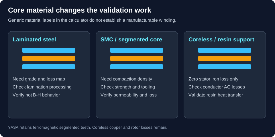
The material labels select nominal screening coefficients. They do not substitute for measured B-H curves, frequency-dependent losses, recoil curves, temperature limits or a manufacturable winding drawing. In particular, a high insulation class does not raise the magnet or adhesive temperature limit.
Source and scope: Gieras, Wang & Kamper — Axial Flux Permanent Magnet Brushless Machines
| System | What the model assumes | Evidence needed for release |
|---|---|---|
| Laminated steel | Generic hysteresis and eddy-current loss terms | Material grade, lamination thickness, processing and measured loss map. |
| SMC | Generic isotropic material and loss terms | Compaction density, strength, permeability and tooling quotation. |
| Coreless | Zero stator iron loss; assumed winding thickness | Conductor eddy loss, resin thermal path and mechanical support. |
| Magnets / winding | Nominal Br; kw=0.945; assumed slot fill | Hot recoil curves, demagnetization, winding phasors and coil-fit trial. |
4. Separate face attraction, net thrust and disc deflection
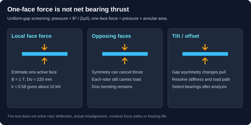
The tool estimates one-face attraction as B²A/(2μ0). For an illustrative B=1 T, Do=220 mm and k=0.58, A≈0.0252 m² and face force≈10.0 kN. Real pole coverage and fringing alter the result. The displayed one-face sensitivity differentiates the assumed force with respect to effective magnetic gap, including magnet reluctance. It is not net UMP or a bearing-life model. Moving a nonmagnetic stator between fixed rotors does not change their separation. For coreless layouts, even the load path differs and needs field analysis.
Source and scope: ISO 21940-11:2016 — Rotor balancing with rigid behaviour
| Question | Screening result | Required next action |
|---|---|---|
| Face force | Local pressure integrated over annulus | Confirm spatial flux and rotor bending with FEA. |
| Net bearing thrust | Unknown; not equal to the sum of face magnitudes | Resolve assembly load path, tilt and thermal growth. |
| Balance / retention | Tip speed flags review only | Agree balance tolerances, correction planes and overspeed protocol. |
5. Cooling coefficients are assumptions, not measured limits
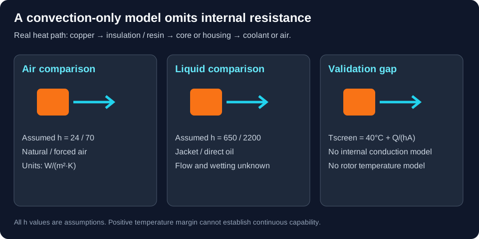
Convection-only temperature = 40°C + stator loss/(h × assumed area). This optimistic simplification omits winding-to-core contact resistance, resin conduction, coolant temperature rise and rotor heating. An apparently cool result cannot establish a continuous rating. UGent’s coupled model demonstrates why electromagnetic losses and boundary-specific heat transfer need joint analysis.
| Cooling choice | Assumed h (W/m²K) | Assumed J review trigger (A/mm²) / unknowns |
|---|---|---|
| Natural air | 24 | 5; airflow, fins, orientation and enclosure unknown. |
| Forced air | 70 | 7.5; fan curve and local flow unknown. |
| Water-glycol jacket | 650 | 15; internal conduction, inlet temperature and flow unknown. |
| Direct oil | 2,200 | 24; wetting, compatibility, scavenging and churning unknown. |
6. Match RMS quantities and verify current as well as voltage
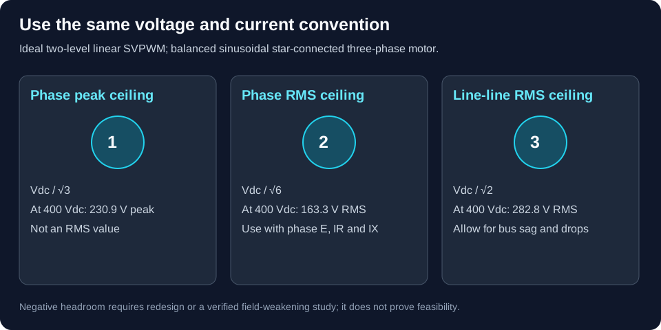
Our convention is a balanced sinusoidal three-phase star winding with phase RMS current and voltage. In ideal linear SVPWM, phase peak ceiling is Vdc/√3, phase RMS is Vdc/√6 and line-line RMS is Vdc/√2. At unity displacement factor, electromagnetic power is 3 Ephase,rms Iphase,rms = Tω. The same convention is used for Ke and Kt. Inverter and friction compensation are not solved by that identity.
| Check | Model method | Limitation / action |
|---|---|---|
| Turns selection | Target E = 0.38 of ceiling at ≤60 V, otherwise 0.65 | Heuristic, resized on every run. It is not a fixed-motor bus sweep. |
| Voltage demand | √((E+IR)²+(ωe L I)²), phase RMS | Approximate sinusoidal steady state; ignores dead time, bus sag and saturation. |
| Headroom | (Vlimit - Vrequired)/Vlimit | Negative: change speed, turns or bus; field weakening is unverified. |
| PWM / insulation | Ripple and terminal overshoot not modeled | Measure L, ripple and cable stress; qualify insulation for the actual inverter. |
7. Release a prototype through evidence gates
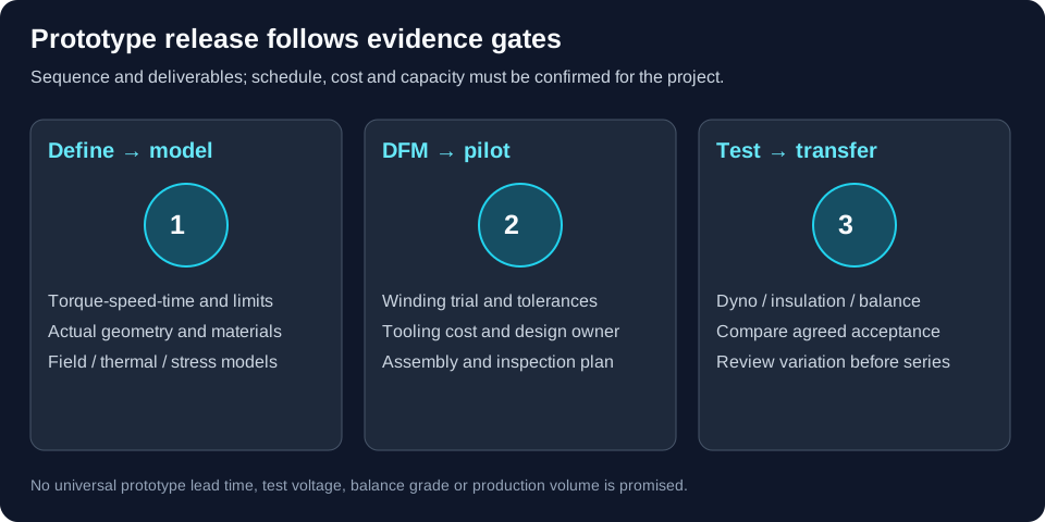
Each step has a deliverable and a decision owner. Schedule and price are unknown until magnet procurement, tooling, winding and test resources are confirmed. The sequence below is a planning framework, not a delivery-time promise.
| Gate | Deliverable | Release decision |
|---|---|---|
| Requirements / concept | Torque-speed-time, interfaces, voltage range, cooling and unknowns | Confirm architecture and design responsibility. |
| Electromagnetic / structural / thermal study | Geometry-specific field, loss, temperature and deflection models | Reject inconsistent targets before tooling. |
| DFM / tooling | Winding trial, tolerance stack, supplier quotes and inspection plan | Agree NRE, yield risk and change ownership. |
| Pilot / validation | Assembly record, balance report, dyno and insulation evidence | Compare measured results against agreed acceptance criteria. |
| Production transfer | Process controls, end-of-line limits and traceability | Release only after variation and capacity are reviewed. |
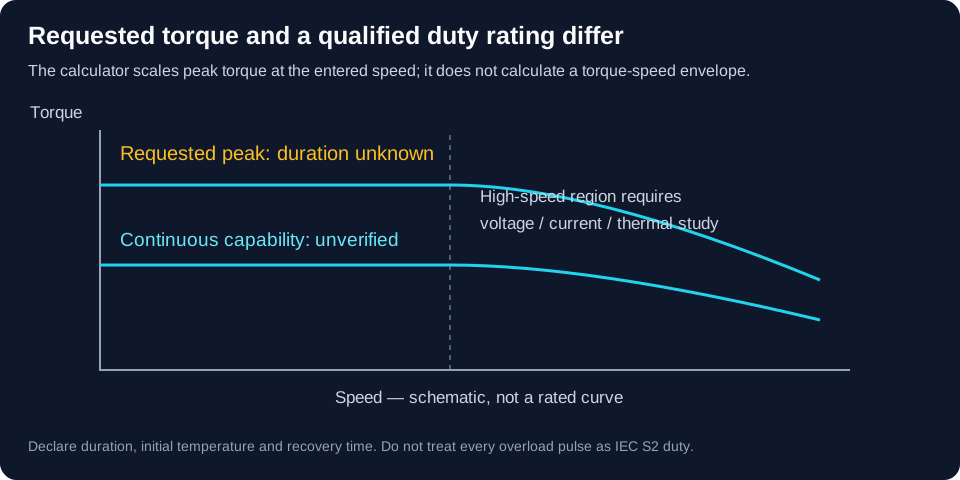
8. A requested peak is not a qualified duty rating
The peak multiplier scales requested torque and same-speed mechanical power only. It does not model duration, saturation, current limits or recovery time. S1 denotes continuous running; S2 is short-time duty with a specified thermal history and duration, not a synonym for any peak pulse. Apply the correct application standard and edition.
Source and scope: IEC 60034-1:2026 — Rating and performance
| Application | Missing duty information | Validation direction |
|---|---|---|
| Robotics | Acceleration pulses, hold torque, repetition and rest periods | Measure joint thermal history, cogging and bearing stiffness. |
| Traction | Drive cycle, bus sag, speed envelope and coolant conditions | Map torque/efficiency on the intended inverter and cooling circuit. |
| Aviation concept | Mission profile, fault cases, redundancy and environmental limits | Define qualification requirements; this preset provides no flight approval. |
9. Three synthetic scenarios: inspect, calculate, validate
These examples run the same model as the tool; they are not customer results or validated designs. Inputs establish the premise; calculated outputs identify the next study. Load each named preset above to reproduce its result. Any voltage or thermal warning is part of the example, not a successful design claim.
Robotics Ultra-Flat Joint Actuator
Premise: 18 N·m at 350 rpm, 48 Vdc, Ø155 × 38 mm.
Method: assumed winding and loss model, then convection-only comparison.
- Requested shaft power
- 0.66 kW
- Modeled efficiency
- 77.6% (unvalidated)
- Voltage headroom
- 53.1% — ample margin
- Convection-only temperature
- 212°C; thermal indicator: exceeded
- One-face force estimate
- 5.16 kN; actual load path unverified
Next: verify winding layout, low-speed heat rejection and bearing stiffness.
High-Performance EV / Motorcycle Powertrain
Premise: 130 N·m at 4000 rpm, 400 Vdc, Ø235 × 80 mm.
Method: assumed winding and loss model, then convection-only comparison.
- Requested shaft power
- 54.45 kW
- Modeled efficiency
- 97.9% (unvalidated)
- Voltage headroom
- 32.4% — ample margin
- Convection-only temperature
- 53°C; thermal indicator: below_assumed_ceiling
- One-face force estimate
- 12.95 kN; actual load path unverified
Next: resolve bus sag, phase current and a measured drive-cycle thermal map.
eVTOL / UAV Coreless Concept
Premise: 45 N·m at 5500 rpm, 600 Vdc, Ø195 × 52 mm.
Method: assumed winding and loss model, then convection-only comparison.
- Requested shaft power
- 25.92 kW
- Modeled efficiency
- 85.9% (unvalidated)
- Voltage headroom
- 30.1% — ample margin
- Convection-only temperature
- 67°C; thermal indicator: below_assumed_ceiling
- One-face force estimate
- 1.05 kN; actual load path unverified
Next: replace coreless gap, conductor AC-loss and oil-drag assumptions with geometry-specific studies.
10. Read manufacturer ratings without inventing a dyno map
The following is a dated reading of the manufacturer’s public page, not independent dyno validation or calibration of this calculator. Separate maxima may occur at different operating points. Earlier or gated datasheet revisions may report different figures; obtain the exact revision, bus, coolant, current and peak duration before a purchasing comparison.
Source and scope: YASA — P400R and 750R manufacturer product page
| Product / public page | Verified public information (accessed 2026-11-06) | Still unknown from that page |
|---|---|---|
| YASA 750R | 700 N·m peak; 200 kW peak; 0–3,250 rpm; 98 mm axial length | Simultaneous operating points, continuous map, mass, bus and cooling test conditions. |
| YASA P400R | Manufacturer describes integration and mechanical/cooling options | Numerical ratings require a revision-controlled sheet; do not fill gaps with estimates. |
11. Risks, costs and alternatives
A concept that fits the envelope can still fail on tooling cost, component temperature, vibration or inverter compatibility. Set stop conditions before commissioning detailed work. These are project planning recommendations, not numerical acceptance standards.
| Risk | Consequence | Mitigation / alternative |
|---|---|---|
| Treating synthetic outputs as guaranteed ratings | Under-sized motor, inverter or cooling system | Reproduce the intended operating point on a prototype; consider an existing qualified motor. |
| Custom segments, magnets and fixtures | NRE, scrap and schedule uncertainty | Request separate tooling and recurring-cost quotes; compare standard geometry. |
| Cooling or high-speed scenario mismatch | Overheating, churning or retention failure | Model real boundary conditions; compare a larger slower motor or geared drive. |
| Standards applied outside scope | Wrong acceptance criteria or false certification | Agree application-specific requirements with the responsible test engineer. |
12. Agree measurements before ordering tooling
Acceptance limits must be agreed for the actual bus, cooling, duty, environment and instrumentation. Neither the insulation standard nor the rotor balancing standard supplies one universal hi-pot voltage, G grade, efficiency tolerance or overspeed percentage for this page.
Source and scope: IEC 60034-18-41:2014, with AMD1:2019 — Type I converter-fed insulation systems
| Measurement | Report with result | Acceptance owner / evidence |
|---|---|---|
| Back-EMF, resistance and inductance | Temperature, speed, RMS/peak and phase/line convention | Electrical design review and comparison to winding model. |
| Torque-speed and efficiency | Bus, phase current, coolant, duration and measurement uncertainty | Customer-approved map and power boundary (motor or drive). |
| Thermal response | Sensors, hot-spot method, inlet/outlet temperature, flow and initial state | Winding, magnet, bearing and adhesive limits. |
| Insulation / balance / structural tests | Applicable standard, revision, waveform, correction planes and test setup | Qualified test plan with agreed thresholds and containment. |
13. AFPM motor custom design FAQ
Sizing and assumptions
What can this AFPM motor custom design tool decide?
It converts an operating point and envelope into a reproducible concept brief. Use it to identify questions for winding, inverter, cooling and structural studies. It does not establish that the target torque is achievable.
Is Di/Do = 0.577 always the best diameter ratio?
No. The illustrative objective k(1-k²) peaks at 1/√3, but assumes a particular loading constraint. At fixed uniform shear stress and fixed outer diameter, annular torque scales with 1-k³ instead. A real optimum needs winding, shaft and thermal constraints.
Why are the displayed efficiency and temperature approximate?
Loss coefficients and winding geometry are assumed, and the thermal calculation uses only 1/(hA) at a 40°C sink. Internal conduction, coolant rise and rotor heating are omitted. A positive margin is not a continuous rating.
Why does changing DC bus voltage also change the winding estimate?
The model resizes series turns toward an assumed back-EMF target for every calculation. This compares rewound concepts, not the same physical motor at a different voltage. Use measured Ke, resistance and inductance to assess an existing motor.
Topology and manufacturing
When should I compare TORUS and AFIR?
Compare the rotor/stator stack, housing heat path, termination count and bearing load path. TORUS uses an internal stator between rotors; AFIR places an internal rotor between stators. This model does not resolve those construction details.
Is a YASA stator coreless?
No. Yokeless means removing a continuous stator yoke, while retaining segmented ferromagnetic teeth. For the synthetic ironless concept select TORUS-NS rather than YASA.
Does a coreless stator remove every motor loss?
It removes modeled stator iron loss, but copper AC loss, rotor magnet eddy loss, mechanical drag and inverter loss can remain. The tool does not include inverter losses.
Which winding layout should be manufactured?
The tool assumes a fixed 0.945 winding factor. Integer pole pairs and a coil count divisible by three are necessary screening checks, not proof of a balanced winding. Verify winding phasors, harmonics, parallel paths and conductor fit before release.
Voltage and thermal limits
Which voltage convention does the calculator use?
Phase-neutral RMS for back-EMF and voltage drops, and phase RMS current for a balanced three-phase star connection. Ideal linear SVPWM phase RMS ceiling is Vdc/√6; Vdc/√3 is the phase peak ceiling. Line-line RMS ceiling is Vdc/√2.
Does a voltage warning prove field weakening will work?
No. Negative headroom indicates that the assumed turns and operating point exceed the ideal voltage limit. Revisit speed, turns and bus voltage; field weakening needs current limits, measured d-q inductances and a magnet demagnetization study.
Does an AFPM motor require a SiC inverter?
No universal semiconductor or carrier frequency follows from topology alone. Specify minimum inductance, allowed ripple, switching losses, current-loop bandwidth and insulation stress, then compare inverter options.
Can a cooling choice guarantee a current density?
No. Values here are assumed comparison coefficients. Flow, wetted area, potting conductivity, contact resistance and allowable component temperatures determine the real continuous current.
Structural integrity and duty
What does the single-sided axial force mean?
It is the uniform-gap Maxwell pressure B²/(2μ0) multiplied by active annular area for one face. It is not multiplied by the number of gaps and is not automatically the net bearing thrust. Resolve the actual load path and disc bending.
Does symmetric dual-rotor construction eliminate structural loads?
Ideal symmetry can cancel net assembly thrust while each rotor still bends under local force. Tilt, bearing play, assembly offsets and thermal growth break symmetry. Use structural and magnetic analysis for net force and stiffness.
When must I add a carbon-fiber sleeve?
This tool cannot select retention. Tip speed is only a review trigger; magnet layout, adhesive, rotor disc geometry, materials, temperature and fault speed govern retention. Require a qualified structural and overspeed test plan.
Is a peak torque multiplier an S2 rating?
No. It only scales the requested torque and same-speed mechanical power. No peak duration, duty history, saturation or inverter peak-current capability is modeled. Declare the full duty cycle and initial thermal state separately.
Prototype and purchasing decisions
Can I send the exported JSON straight to an FEA solver?
No. It is a screening brief containing inputs, synthetic results and limitations. A solver needs actual geometry, materials, winding connections, mesh and boundary conditions.
Can I compare catalog peak torque and peak power at one speed?
Only when the datasheet identifies a simultaneous operating point. Separate maxima, coolant conditions, voltage and peak duration cannot be combined into a fabricated torque-speed curve.
What should an RFQ include?
Send torque-speed-time history, bus range and current limits, envelope and shaft interfaces, cooling conditions, environment, target quantities and the required acceptance plan. Mark assumptions and unknowns explicitly.
How long does a custom prototype take?
There is no supported universal delivery time. Obtain a scoped schedule after winding, magnet, tooling and test capacity are reviewed. Freeze acceptance criteria and design ownership before ordering tooling.
14. Sources, dates and evidence boundaries
Published · Reviewed · Next review . Published by AFPM Motor. Review sooner if the model, references or applicable standards change.
Checked 2026-11-06. Public publisher records, author repositories and manufacturer pages are linked below. Standards catalogue abstracts confirm scope and editions; full acceptance clauses require the applicable standard and test plan. Formula derivations and synthetic coefficients are identified separately above. No independent prototype test dataset supports this calculator.
- Gieras, Wang & Kamper — Axial Flux Permanent Magnet Brushless Machines ↗
Springer, second edition, 2008
Publisher record for AFPM construction and analysis. The simplified coefficients in this calculator are our assumptions, not calibrated textbook data.
- Vansompel et al. — Coupled electromagnetic and thermal analysis of an axial flux PM machine ↗
IEEE Transactions on Magnetics 51(11), 2015; UGent author repository
Coupled convection and electromagnetic analysis, validated on a particular 4 kW YASA machine. Does not establish universal heat-transfer or current-density limits.
- IEC 60034-1:2026 — Rating and performance ↗
IEC, edition 15, published 2026-03-13
Replaces the 2022 edition. Check application scope: rail and road vehicle machines are directed to IEC 60349; aerospace may have additional requirements.
- IEC 60034-18-41:2014, with AMD1:2019 — Type I converter-fed insulation systems ↗
IEC public catalogue and consolidated edition listing
Qualification and quality-control framework. The public abstract does not prescribe one universal RPDIV or hi-pot voltage for every motor.
- ISO 21940-11:2016 — Rotor balancing with rigid behaviour ↗
ISO; amendment 1 published 2022
Residual unbalance, correction planes and tolerances for rigid rotors. Replaces ISO 1940-1; it is not a universal overspeed or retaining-sleeve rule.
- YASA — P400R and 750R manufacturer product page ↗
Undated manufacturer page, accessed 2026-11-06
Public 750R headline ratings: 700 N·m peak, 200 kW peak, 0–3,250 rpm and 98 mm axial length. Request a revision-controlled sheet for operating conditions; other sheet revisions may differ.
Turn the concept into a reviewable RFQ
Copy or export the tool brief and add your torque-speed-time history, bus range and inverter current limits, maximum envelope, shaft interfaces, cooling inlet/flow, environment, quantities and acceptance criteria. If a required input is unknown, send the known operating targets and mark the rest “to be confirmed”.
Ask for design scope, tooling and recurring costs, validation deliverables and a project-specific schedule. Scope and availability must be confirmed before committing to simulation, prototype delivery or performance.
Inquiry Email
Please include application, peak/continuous torque, speed range, voltage/current limit, outer diameter, axial length, cooling method, quantity, and drawings or reference samples.
Instant Chat
WhatsApp Engineering Support
Share torque-speed, package, cooling, and sample quantity in the first message.