
AFPM Motor Design for Manufacturing (DFM)
AFPM motor design for manufacturing starts with planar airgaps and magnetic attraction. These make axial flux motors distinct from radial machines. Evaluate mechanical tolerance stackups, rotor disc deflection, magnet retention stresses, and stator producibility before freezing tooling.
Last reviewed · Next review · By AFPM Motor
Request an OEM DFM review →Four decisions before tooling release
Clearance is a combined budget
Review both discs, supports, thermal drift and measured tolerances; a high screening ratio cannot release the design.
Evidence, limits and next action →Retention capacity is unknown
Obtain geometry-specific load paths and qualified hot/aged properties before choosing containment.
Evidence, limits and next action →Process economics require quotes
SMC offers a manufacturing route; no public evidence here establishes an exact cycle, price or annual break-even.
Evidence, limits and next action →Qualification differs from routine EOL
Choose test levels and coverage for the winding, converter and application; do not copy universal test voltages.
Evidence, limits and next action →Evidence checked 2026-11-06. Chapters distinguish cited source scope from editorial engineering guidance and illustrative assumptions. No verified customer production outcomes are available.
Reproduce the default DFM screening result
This screenshot records an actual browser run on 2026-11-06 using model 2026.11.06-dfm-v2 and the EV illustrative preset. It shows software output, not a physical motor test, customer result or manufacturing qualification. The report and default result remain readable without JavaScript; editing and exports require it.
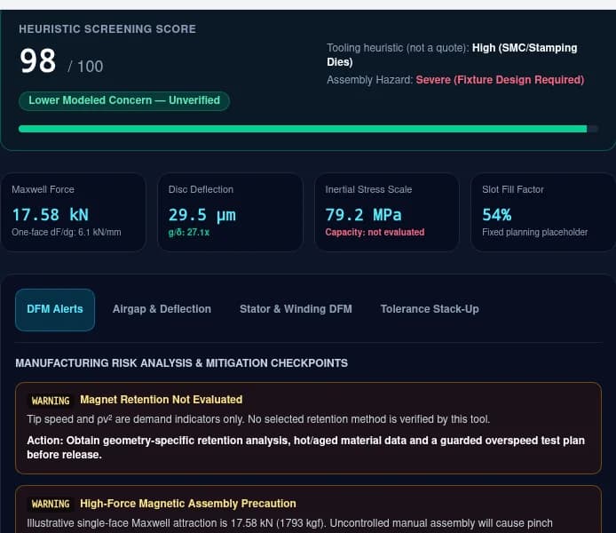
All reproducible inputs and result data
{
  "outerDiameterMm": 260,
  "diameterRatio": 0.58,
  "airGapMm": 0.8,
  "ratedSpeedRpm": 7500,
  "polePairs": 10,
  "statorSlots": 12,
  "backIronThicknessMm": 10,
  "magnetThicknessMm": 6,
  "annualVolume": 5000,
  "topology": "yasa",
  "statorCoreType": "smc_segmented_teeth",
  "magnetRetention": "cfrp_sleeve"
}
Download the recorded inputs, complete outputs and provenance (JSON)1. Define the manufacturing load path before the process
An AFPM planar gap is sensitive to axial displacement and disc tilt. Separate local magnetic loading on a rotor face from the net load carried by the shaft and bearings: opposing forces may cancel globally while both discs still bend. This report turns those distinctions into a review package. The tables are engineering review guidance; unverified quantities are explicitly identified.
Reference & Scope: Gieras, Wang & Kamper — Axial Flux Permanent Magnet Brushless Machines
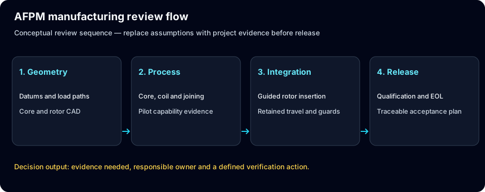
| Decision | Axial-flux concern | Required evidence |
|---|---|---|
| Disc support | Hub, fasteners and pockets change stiffness | Sectioned CAD and structural boundary conditions |
| Bearing load | Net thrust depends on topology and external loads | Complete free-body diagram, including assembly |
| Process choice | Core and winding geometry constrain tooling | Supplier DFM feedback and pilot build |
2. Use disc deflection as sensitivity, not clearance approval
The tool uses F = B²A/(2μ₀) over the entire annulus and δ = 0.125·P·(Ro−Ri)⁴/D, with D = Et³/[12(1−ν²)]. The coefficient is uncalibrated and the pole coverage is assumed to be 100%. It is useful for comparing thickness at fixed geometry, but omits hub flexibility, pockets, contact, both rotor faces and dynamic effects. A large g/δ ratio is not proof of safe operation.
Reference & Scope: Gieras, Wang & Kamper — Axial Flux Permanent Magnet Brushless Machines
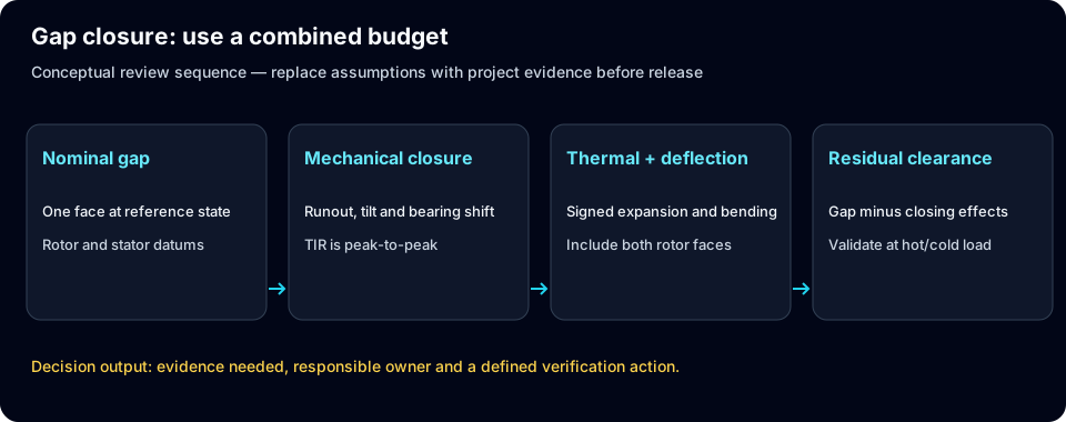
| Change at fixed geometry | Model response | Release evidence |
|---|---|---|
| Double plate thickness | Deflection falls by approximately 8× | FEA with actual hub, magnets and fasteners |
| Increase flux density | Pressure increases with B² | Spatial electromagnetic force map |
| Reduce airgap | Flux and force change together | Coupled minimum-gap assessment at temperature |
3. Keep deterministic closure out of a statistical variance claim
The default 240 mm scenario assumes mechanical magnitudes of 24, 30, 30 and 20 µm, plus 24 µm directional thermal closure. Their linear total is 128 µm. Mechanical RSS is 52.7 µm; adding thermal closure gives 76.7 µm. No measured distributions, independence or sigma level are supplied. Runout TIR is peak-to-peak; convert it using the actual datum and waveform before using a signed gap contribution.
Reference & Scope: Gieras, Wang & Kamper — Axial Flux Permanent Magnet Brushless Machines
| Contribution | Default placeholder (µm) | What must replace it |
|---|---|---|
| Rotor axial error | 24 | Measured gap contribution with datum definition |
| Bearing movement | 30 | Load/temperature-dependent axial movement |
| Stator mounting error | 30 | Mounting flatness and tilt projected onto gap |
| Magnet thickness | 20 | Drawing tolerance and assembled adhesive layer |
| Directional thermal closure | 24 | Signed multi-material expansion model |
| Worst-case / RSS + thermal | 128 / 76.7 | Validated stack including both rotor faces |
4. Compare core processes using qualified properties
Höganäs describes insulated iron powder formed into complex shapes by powder metallurgy for three-dimensional flux paths. This supports SMC as a process candidate, not a universal winner. Compare loss at the actual electrical frequency and flux waveform, mechanical handling, dimensional control and supplier capability. Coreless stators remove stator core losses but still incur copper, magnet and other system losses.
Reference & Scope: Höganäs — Soft magnetic composites
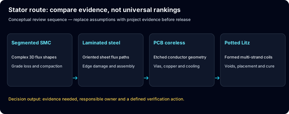
| Route | Manufacturing opportunity | Risk and next evidence |
|---|---|---|
| Segmented SMC | Net-shaped teeth and accessible coil assembly | Compaction density, ejection damage and grade loss curves |
| Tape-wound steel | Laminated flux paths | Cut-edge damage, insulation and winding access |
| PCB coreless | Repeatable etched conductor geometry | Copper cross-section, vias, cooling and dielectric spacing |
| Potted Litz coreless | Formed coil layout | Void control, placement, resin cure and heat path |
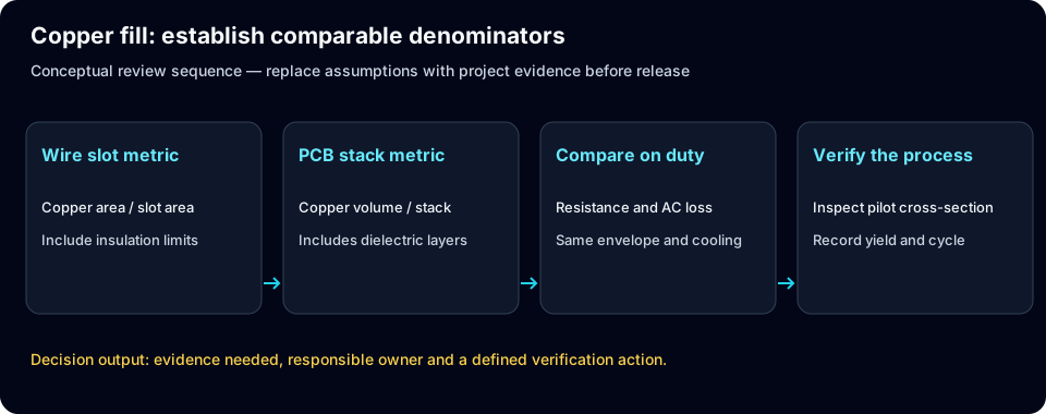
5. Define the copper-fill denominator before comparing routes
The tool uses fixed planning placeholders of 54%, 42%, 24% and 46% by core route. They are not measured yields, achievable maxima or outputs of a slot-geometry calculation. PCB stack copper fraction and copper inside an insulated wire slot are different metrics. Compare active copper area, resistance, AC loss and thermal performance on the same motor envelope. Pole and slot counts are RFQ inputs only; this screen does not validate the winding layout.
Reference & Scope: Gieras, Wang & Kamper — Axial Flux Permanent Magnet Brushless Machines
| Route | Key process constraint | Pilot measurement |
|---|---|---|
| Segmented bobbin | Bend radius and insulation clearance | Copper area / declared slot area; damaged enamel rate |
| Toroidal winding | Shuttle access and back-turn length | Complete-core cycle time and resistance |
| PCB traces | Layer thickness, trace/via spacing | Finished copper section and hotspot temperature |
| Formed Litz | Compaction and impregnation | AC resistance, voids and conductor position |
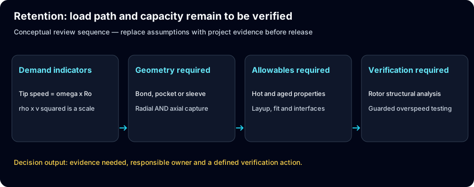
6. Retention capacity needs geometry and qualified allowables
The computed ρv² quantity is an inertial stress scale, not adhesive shear stress or sleeve stress. It cannot be divided by a catalogue tensile strength to obtain a valid retention safety factor. A thin outer band may react radial motion without capturing axial lift. Every retention option therefore reports capacity as not evaluated. Carbon-fibre composites can conduct electricity; laminate orientation and harmonics determine their loss contribution.
Reference & Scope: Gieras, Wang & Kamper — Axial Flux Permanent Magnet Brushless Machines
| Concept | Unknown required for analysis | Validation path |
|---|---|---|
| Recessed pockets | Ligament area, stress concentrations and axial capture | Combined rotor FEA and guarded spin testing |
| CFRP sleeve/band | Layup, thickness, prestress, interface and temperature | Laminate allowables, cure QA and overspeed test |
| Metal ring | Interference, yield, thermal mismatch and harmonics | Contact/stress model and loss assessment |
| Adhesive only | Bond area, surface preparation, ageing and peel | Hot/aged coupons and full-rotor qualification |
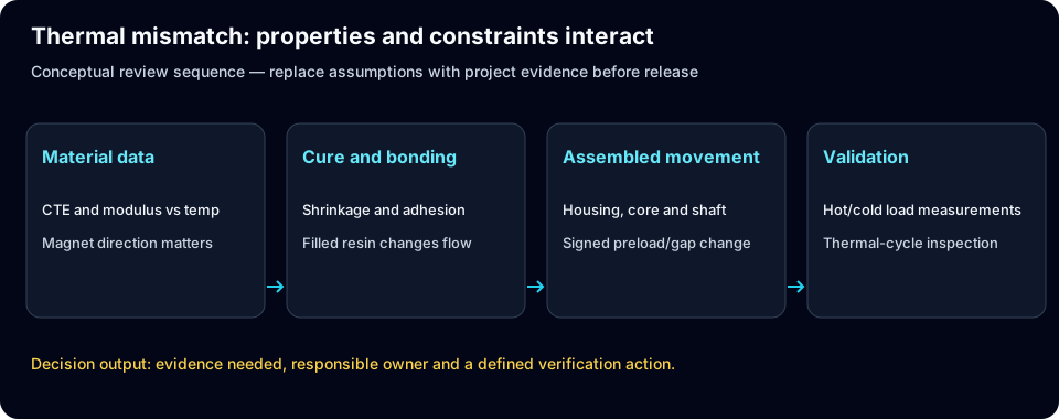
7. Treat potting and thermal growth as a coupled design
A resin recipe cannot be selected from CTE alone. Cure shrinkage, modulus, glass transition, moisture, filler loading and adhesion all affect stress and manufacturability. Magnet properties and expansion can be directional. The tool has no temperatures or material stack lengths, so its thermal term is only a placeholder. Replace it with signed hot/cold displacement estimates and verify the assembled stator.
Reference & Scope: Gieras, Wang & Kamper — Axial Flux Permanent Magnet Brushless Machines
| Interface | Potential failure | Evidence and mitigation |
|---|---|---|
| Resin / copper | Cure or cyclic interface cracking | Grade-specific data; thermal-cycle cross sections |
| Resin / core | Debonding and altered heat path | Adhesion trials and void inspection |
| Housing / shaft | Changed preload or axial location | Hot/cold dimensional stack and bearing review |
| Magnet / rotor | Bond shear, peel or gap change | Directional expansion and hot bond qualification |
8. Select bearings from net loads and stiffness
Do not apply the one-face magnetic force directly as bearing thrust in every topology. Calculate net shaft loads, external pump or propeller thrust, imbalance, transients and preload first. A back-to-back angular-contact pair is one candidate for moment stiffness; deep-groove, tapered or cross-roller options may also fit a particular duty. Bearing size, speed, lubrication and thermal growth decide the actual capacity and life.
Reference & Scope: Gieras, Wang & Kamper — Axial Flux Permanent Magnet Brushless Machines
| Candidate | Tradeoff | Required check |
|---|---|---|
| Angular-contact DB / DF | Moment stiffness versus alignment sensitivity | Manufacturer stiffness, life and preload calculations |
| Tapered roller pair | Axial/radial capacity versus drag | Thermal preload and lubrication |
| Cross-roller cartridge | Compact moment support versus speed/drag | Supplier operating envelope |
| Deep-groove arrangement | Simple sourcing, conditional axial capability | Actual load, clearance and gap displacement |
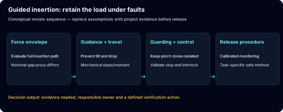
9. Design the insertion fixture for a verified force envelope
Magnetized discs can create crush and ejection hazards. The tool estimates force at the nominal operating gap, not the entire insertion path or a fixture-rated maximum. Define a guarded, guided insertion process with controlled travel and a retained load path under power loss. Feed rate, actuator choice, interlock performance and fixture material require a task-specific assessment; no fixed speed or hydraulic requirement applies to all motors.
Reference & Scope: Gieras, Wang & Kamper — Axial Flux Permanent Magnet Brushless Machines
| Fixture function | Design question | Verification artifact |
|---|---|---|
| Guidance | Can discs tilt or side-load the guides? | Stiffness and alignment check |
| Travel retention | What happens after drive or power failure? | Mechanical restraint and fault test |
| Guarding / interlocks | Can operators reach a moving pinch zone? | Validated hazard assessment and procedure |
| Force monitoring | What load stops the insertion? | Calibrated load envelope and stop validation |
10. Separate qualification from routine end-of-line tests
IEC 60034-18-41 covers qualification and quality-control tests for Type I converter-fed winding insulation. Its public scope does not establish a universal high-pot or surge voltage for every motor. Set voltage, pulse rise time, temperature, duration and pass criteria from the actual insulation system and applicable requirements. A long full-load thermal run may be a qualification or sample test rather than an economical 100% EOL step.
Reference & Scope: IEC 60034-18-41:2014+AMD1:2019 — Type I converter-fed insulation
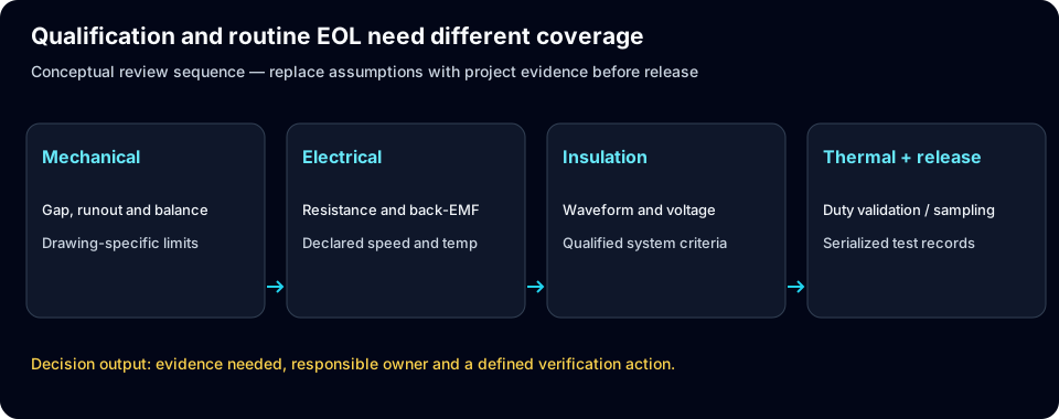
| Test family | Evidence sought | Acceptance limit source |
|---|---|---|
| Gap / runout | Assembled minimum clearance and datum traceability | Released stack and metrology uncertainty |
| Back-EMF / resistance | Phase balance and winding/magnet defects | Validated design baseline at declared speed/temperature |
| Insulation | Withstand and converter stress capability | Qualified system and applicable standard clauses |
| Thermal / load | Hotspot and cooling performance | Duty and cooling validation; sampling policy |
| Rotor balance | Residual unbalance and correction planes | Selected ISO 21940 procedure and rotor behaviour |
11. Quote the process before claiming a volume break-even
Public evidence here does not establish tooling prices, cycle times, scrap rates or unit costs for a defined AFPM product. Treat them as unknown until the supplier quotes an agreed drawing and test scope. Compare total good-unit cost, including inspection, yield, tool maintenance, rework, logistics and working capital. For illustrative arithmetic only, an incremental $40,000 tool that saves $50 per accepted unit breaks even at 800 accepted units, before financing or capacity effects; this is not an annual market threshold.
Reference & Scope: Höganäs — Soft magnetic composites
| Cost element | Known now | Required quote input |
|---|---|---|
| Tooling / NRE | Route and expected volume | Die, fixture, programming and ownership scope |
| Cycle / yield | Not established | Pilot cycle on the same part and accepted-unit yield |
| Inspection / EOL | Test families only | Coverage, station time and calibration cost |
| Break-even | ΔNRE / saving per good unit | Comparable quoted variable costs and demand horizon |
12. Make design freeze a documented release decision
Use the export to open a review, not to sign off tooling. Screening status must be reconciled with CAD, measured tolerances, load cases, supplier capability and qualification results. Where evidence is missing, assign an owner and hold the affected release decision. ISO 21940-11 addresses rigid-rotor balance; it is not a magnet-containment certificate.
Reference & Scope: ISO 21940-11:2016 — Rotor balancing, rigid behaviour
| Release gate | Required artifact | Owner |
|---|---|---|
| Clearance and stiffness | Coupled force/deflection/thermal stack | Mechanical lead |
| Retention and overspeed | Geometry-specific analysis and test report | Rotor structural lead |
| Core and winding process | Pilot build, loss and insulation results | Manufacturing / electrical lead |
| Safe assembly | Validated fixture and operating procedure | Tooling / plant safety lead |
| EOL and sourcing | Acceptance plan, traceability and quoted scope | Quality / sourcing lead |
13. Illustrative scenarios: compare before requesting validation
Four hypothetical scenarios share the tool’s presets and model version. They show how to open a design review; they are not customer case studies or measured production improvements. Load the matching preset to reproduce its inputs and export the assumptions. Compare one input at a time before requesting geometry-specific analysis and a production-representative pilot. Retention capacity, cost, yield and certification remain unknown for every scenario.
EV traction preset
Illustrative model scenarioDiameter / gap
260 mm / 0.8 mm
Speed
7500 RPM
One-face force proxy
17.58 kN
Plate deflection proxy
29.5 µm
Retention capacity
Not evaluated
Review retention and guided assembly. No customer test data or production history is implied.
Coreless propulsion preset
Illustrative model scenarioDiameter / gap
180 mm / 1.2 mm
Speed
4500 RPM
One-face force proxy
4.65 kN
Plate deflection proxy
21.6 µm
Retention capacity
Not evaluated
Review effective magnetic gap and stator thickness. No customer test data or production history is implied.
Industrial direct-drive preset
Illustrative model scenarioDiameter / gap
380 mm / 1.5 mm
Speed
900 RPM
One-face force proxy
32.45 kN
Plate deflection proxy
24.2 µm
Retention capacity
Not evaluated
Review net bearing load and external thrust. No customer test data or production history is implied.
Robotic actuator preset
Illustrative model scenarioDiameter / gap
130 mm / 0.7 mm
Speed
10000 RPM
One-face force proxy
2.91 kN
Plate deflection proxy
3.1 µm
Retention capacity
Not evaluated
Review datum control and winding verification. No customer test data or production history is implied.
14. Frequently Asked Questions: AFPM Motor DFM
Practical answers to 20 critical engineering, tolerancing, tooling, and commercial sourcing questions across four categories.
Mechanical Tolerances & Deflection
Why does axial runout matter?
Axial displacement and disc tilt directly change the planar gap. Both rotor faces, support stiffness and thermal conditions must be included; chapter 3 defines the stack.
Is a g/δ ratio of four a safe design?
No. The tool uses ratios only to prioritize review. It has no validated support geometry or complete dynamic gap budget, so it cannot set a universal safe ratio.
Why does thickness have a cubic effect?
In the fixed-geometry plate approximation D = Et³/[12(1−ν²)]. Doubling thickness multiplies that rigidity by eight. Changes to supports, pockets or material require a new analysis.
Does RSS mean 3σ?
Only if the component inputs represent compatible statistical quantities with justified distributions and correlations. Here they are placeholders; mechanical RSS plus directional thermal closure carries no sigma claim.
Is TIR a ± tolerance?
No. TIR is the full indicator excursion. Relating it to a one-sided gap contribution requires the datum, geometry and waveform. Do not enter TIR directly as a signed amplitude.
Stator Core & Winding Producibility
When should SMC be considered?
Consider SMC for complex three-dimensional flux paths and net-shaped components, then compare supplier loss curves, mechanical capability and quoted tooling. Höganäs supports the process concept, not a universal economic threshold.
Can PCB and wire slot fill be compared directly?
Not without defining the same denominator. Compare active copper section, resistance, AC loss, cooling and envelope rather than ranking two different fill metrics.
Does the tool validate pole/slot combinations?
No. Counts must be whole numbers and are preserved in the RFQ export, but phase layout, winding factor, electrical frequency loss and torque ripple need electromagnetic design checks.
Is VPI mandatory for every coreless stator?
No. Potting, vacuum casting or impregnation must suit the insulation and structural design. Validate voids, cure, dielectric performance and heat transfer for the selected process.
How should coil joints be qualified?
Choose welding, soldering or mechanical joining from conductor and insulation constraints. Measure joint resistance, mechanical integrity and thermal damage on production-representative samples.
Magnet Retention & Assembly Safety
Why is retention capacity not evaluated?
The inputs omit magnet dimensions, bond area, pocket ligament, sleeve thickness, layup, interference and qualified aged material allowables. ρv² alone cannot provide a retention safety factor.
Is CFRP electrically nonconductive?
Carbon fibres are conductive and composite conductivity is directional. Analyse the chosen layup and harmonics; an electrically insulating resin does not make the complete sleeve loss-free.
Does an outer band also capture axial lift?
Not necessarily. It may react radial motion while leaving an axial escape path. Review the actual load path and geometry for all relevant load cases.
Does low estimated force permit manual assembly?
No. The value is a nominal-gap proxy, not a validated assembly force envelope. Define guarding, retained travel and fault behaviour in the fixture review.
Which resin CTE guarantees no cracks?
No single CTE guarantees integrity. Compare modulus, cure shrinkage, adhesion, glass transition, moisture and thermal cycling using grade-specific data and assembled samples.
Tooling Capex & Production Scaling
What tooling budget should be assumed?
No verified budget is available for this part. Obtain a scoped quote covering tooling ownership, maintenance, metrology, insertion fixtures, EOL coverage and expected accepted-unit yield.
Does face attraction equal bearing thrust?
Not in every topology. Opposing rotor forces may balance in the shaft while discs remain locally loaded. Add external loads and preload using a complete free-body diagram.
Are 2.2 kV high-pot and 3 kV surge universal EOL limits?
No. Use the qualified winding/converter system and applicable standard clauses. IEC 60034-18-41 provides a qualification and quality-control framework; it does not justify these universal values.
What belongs in the DFM review package?
Include CAD and datums, torque-speed duty, voltage and converter waveform, hot/cold conditions, gap budget, retention concept, volume horizon and proposed qualification/EOL plan. Attach the screening export as assumptions, not approval.
Is there an exact annual SMC break-even volume?
No. Divide incremental NRE by the quoted saving per accepted unit over the programme horizon, then account for demand, yield, capacity, maintenance and financing. Chapter 11 shows illustrative arithmetic only.
15. Technical References & Evidence Sources
Published · Reviewed · Next review . Published by AFPM Motor. Referenced standards and peer-reviewed literature:
- Gieras, Wang & Kamper — Axial Flux Permanent Magnet Brushless Machines ↗
Springer, second edition, 2008; publisher record checked 2026-11-06
Background on AFPM topologies and construction. The public publisher record does not validate this tool’s plate coefficient, thresholds, costs or sample results.
- Höganäs — Soft magnetic composites ↗
Manufacturer material overview; accessed 2026-11-06
Insulated iron powder and powder metallurgy enable complex three-dimensional magnetic circuits. Grade-specific properties and process economics require supplier data; this is a manufacturer source, not an independent benchmark.
- ISO 21940-11:2016 — Rotor balancing, rigid behaviour ↗
ISO, 2016, with Amendment 1:2022; catalogue checked 2026-11-06
Procedures, residual-unbalance tolerances and correction-plane allocation for rigid rotors. It does not certify magnet containment or mandate a universal AFPM balance grade. Flexible rotors require another assessment.
- IEC 60034-18-41:2014+AMD1:2019 — Type I converter-fed insulation ↗
IEC consolidated edition 1.1, 2019, including December 2020 corrigendum; catalogue checked 2026-11-06
Qualification and quality-control framework for converter-fed winding insulation. Test voltage, waveform and routine versus type-test allocation depend on the winding and converter; no universal 2.2 kV or 3 kV gate is asserted here.
Request an OEM DFM Tooling & Producibility Review
Transitioning an axial flux motor design from FEA simulation to repeatable serial production requires disciplined mechanical tolerancing, structural disc stiffness validation, and magnetic assembly tooling. Export your DFM brief from the calculator above or send your 3D CAD step files and duty specifications to our manufacturing engineering team.
Inquiry Email
Please include application, peak/continuous torque, speed range, voltage/current limit, outer diameter, axial length, cooling method, quantity, and drawings or reference samples.
Instant Chat
WhatsApp Engineering Support
Share torque-speed, package, cooling, and sample quantity in the first message.